A few months ago at the NMRA (BR) convention in Bournemouth I was asked by a fellow modeller, Mike Dobson, if 3D printing could be used to produce some replacement gears for one of his O Gauge locomotives. In this post I will share with you how we achieved just that.
The locomotive in question is a Rivarossi O Gauge F9; although the test locomotive is a Red Caboose GP9 shell with a Rivarrossi F9 chassis in it. Below is a shot of the locomotive on Mike’s layout.
The gear which Mike wanted printed is the final gear in the transmission. This is the gear is on the locomotive axles. The original plastic gear had split, as you can see in the picture below, and no longer clamped onto the axle but simply spun in place. The gear is press fitted onto the metal axle and friction between the plastic and the metal means the axle will rotate with the gear. The plastic Rivarossi used for their gears is rather brittle and it’s a common problem for this to split like this.
The first thing to do was to measure and draw the gear in the 3D model. Below is a rendering of a pair of gears.
Then it was off to the printer and for these gears I used Shapeways Frosted Ultra Detail material, the first set is shown below. As well as being Shapeways highest detail material it is also one of the most accurate. And it has very similar properties to the original gear material although not so brittle, but mainly that it has a hard finish so should be long wearing. I felt that the White Strong & Flexible material, despite being cheaper, may lead to the gear teeth being uneven and also may wear down very quickly.
With the gears successfully printed it was time to try them out on the F9 chassis. Below you see the underside of the F9 with a new 3D printed gear on each chassis axle. As this was the first run of gears there was a bit of trial an error involved with the fit onto the axle. If the hole through the middle was too small then pushing the gear onto the axle will cause the gear to split. If the hole is too big there will not be enough friction to rotate the axle. With the first print I was slightly too big on the hole. This has now been corrected and the next set should be spot on. However the main test was to see how well the 3D printed gears stood up to the punishment of an O Scale motor so Mike friend and fellow O-scaler Steve Morris reamed out the gears and fitted a brass sleeve inside. The gear was now a tight fit onto the sleeve and the sleeve was a tight fit onto the axle.
Below are some close-ups of the gears in place and you can just make out the brass sleeve.
With the gears in place and the locomotive fully reassembled it was time for a test. As well as the nicely scened sections of Mike’s layout he also has a staging area above which is reached by a 2.5% curved grade. You can see this below along with Mike’s test train of six loaded ore cars, four box cars and a caboose. This grade also forms part of a continuous run so the test locomotive could be left to trundle round with its train for a few hours. This was a good check for wear on the gears, and after several hours there was none.
Here is video of the train running through the station and then up that curved grade.
The second set of gears with the correct hole size will be going to print soon and Mike will be doing some more tests with them. Once we know that they are correct I will make them available for everybody who needs replacement gears for their locomotive.
If you have similar gears on a locomotive that need to be replaced and would like to try a 3D printed replacement please contact me through the contact page or drop me an e-mail.
In last week’s post I started showing you how my new N Scale project is coming on, Alco’s C-855. And as promised in this week’s post I am going to show you how I intend to lengthen the donor chassis for this locomotive.
The chosen chassis, as modeled below, for the C-855 is going to be Con-Cor’s 4500 Gas Turbine/GE U50 chassis.
Although the chassis has the right trucks etc for the C-855 they are at the wrong centers and need to be spread apart by 10mm. That doesn’t sound a lot but in N scale it can make a huge difference visually, it’s 1.6 meters (5′ 3″) on the real locomotive.
I looked at several ways to do this and each time found a reason why it couldn’t be done that way. The main issue is the motor; it is centrally positioned in the chassis with two drive shafts powering the two furthest sets of trucks. The two inner ones are not powered. Spreading the trucks will also mean the drive shafts will no longer reach them. And if only one end is lengthened it may cause an unbalanced load to be applied to the motor. The motor hangs down in the frame and on the 4500 Gas Turbine/GE U50 this is concealed by a fuel tank mounted between the trucks. On a side note, the 4500 Gas Turbine didn’t have a fuel tank but a battery box in this location and I already offer a 3D printed replacement part to correct the 4500 Gas Turbine which you can find here.
The C-855 side frames hang down in this location which is a visual aspect quite unique to the C-855. You can see this on the shell render below. Again if the donor chassis was only extended at one end the areas where the motor hangs down would be visible on one side of the frame.
Therefore my only choice is to leave the motor in the center of the chassis and extend it in both directions. Because the chassis provides the strength and weight for the locomotive I need to do this in such a way that it doesn’t compromise the chassis. Also I want to make it easy to do.
I decided to totally remove the center section which holds the motor in place and replace it with a longer 3D printed part. Below you can see a rendering of the chassis showing were I plan to remove the section.
And then below is a rendering showing the main parts in the correct place.
The new section in the middle will actually need to be two parts, as pictured below. This is because the top of the chassis conducts electricity from one rail and the bottom from the other. Also adding more material into the 3D print adds unnecessary cost.
The two new parts have been drawn to match the sections which have been removed so they will clamp the motor in the right place, as you can see in the rendering below. The new parts will be printed in stainless steel which will maintain the weight required by this locomotive. I will also offer the extension pieces in plastic as a cheaper alternative. Where I plan to cut the chassis will form a natural step, making the joint to the new sections stronger.
The last part of the puzzle are the drive shafts which will now be equally 5mm too short. To resolve this I will be 3D printing an extension piece for both. Below is a rendering of one of the standard drive shafts. The circular cup gear on the end fits over the drive gear on the motor.
To extend this I have simply designed a part that will fit into this cup gear with the same configuration on the outside as shown below.
The new part will be glued into the drive shaft completing the extension.
With the whole thing assembled the lengthened chassis should look like this.
One more modification to the chassis will also need to be made at the cab end so that it fits into the C-855 shell. But until I finish the design work for the shell I won’t know the extent of the modification, so I will share that with you once I have 3D printed the new parts and have a real C-855 chassis to show you.
As I have said before I have a passion for the large locomotives of the Union Pacific Railroad and in this post I will share with you the first stages of my designs for Alco’s massive Century 855.
This locomotive, or rather set of three locomotives, were Alco’s answer to UP request for a 15000 horsepower set of locomotives to replace their Gas Turbines. The Gas Turbines were becoming increasing more expensive to run. 15000 horsepower could have been obtained by simply running six 2500 horsepower locomotives together such as GP35s. However UP were concerned that the running costs of six locomotives would be considerably higher than say three much larger locomotives producing the same overall power. So UP approached three of the main locomotive builders of the time; Alco, Electro-Motive Division (EMD) and General Electric (GE).
All three companies produced big locomotives for UP to trial that shared two main principles; they were all twin-engine units riding on a single chassis and they all had eight powered axles.
EMD’s offering as pictured below was the DD35, pre runner to the DD35A & DD40AX. The DD35 was effectively two GP35 bodies joined together riding on a pair of four axle trucks. It had no cab and was used as a booster unit. EMD’s demonstrator set consisted of two 2500 horsepower GP35 locomotives and two 5000 horsepower DD35 boosters. Together they gave the 15000 horsepower UP were looking for. This is a model I have already produced for N Scale and you can find it here.
GE’s offering was the U50, as shown below paired with a EMD DD35. This locomotive was built up from a pair of U25B locomotives on a singe chassis. The chassis and trucks for the U50 came from retired 4500 Gas Turbines that the UP had traded back to GE. So, as with the 4500 Gas Turbines, the U50 rode on four two axle trucks grouped in pairs and connected by span bolsters. Unlike the DD35 these had cabs and could be used as single 5000 horsepower locomotives or in a set of three to meet UP’s requirement. The U50 below is a production model made by Con-Cor.
Alco’s answer to UPs request was the C-855. The C stands for Century and this locomotive was part of their Century series of locomotive that covered everything from small switching locomotives to these massive road engines. The 855 refers to the numbered powered axles, eight in this case, and the horsepower. The pair of sixteen cylinder Alco 251C diesel engines put out 5500 horsepower and in 1964 this made the C-855 the most powerful locomotive for its time.
As with the U50 UP traded in retired 4500 Gas turbines but Alco only used the trucks for their new locomotive, the chassis was a totally new design. Alco built three locomotive as their demonstrator set consisting of a pair of A units with cabs and one cabless B unit. Together the set produced a formidable 16500 horsepower and had potential for being the dominant locomotive. But sadly due to poor performance UP did not order any more. The original set of three stayed in general service based out of North Platte, Nebraska for nine years before being scrapped in February 1972.
These locomotives are considered by many to be very ugly with their lumps and bumps and I am inclined to agree. However I think that they are so ugly they become interesting. These have never been mass-produced by a mainstream manufacturer in N Scale, probably because only three were ever made and they didn’t last that long.
The first thing I needed to sort out for this locomotive was the power chassis and for this I am going to use Con-Cor’s 4500 Gas Turbine/U50 power chassis as pictured below. This made sense as the trucks are the same.
The downside to using this chassis is it’s too short. As Alco only reused the 4500 Gas Turbine trucks and not the chassis they repositioned the trucks further apart. As this model is N Scale I did look at whether a bit of modeler’s license would be used, if the difference was small it may not be noticed. But as I started taking measurements it soon became clear that there was a fairly big difference and I wanted to get the locomotive right. To overcome this I will be 3D printing a metal extension piece to fit into the middle of the chassis. This will push the trucks further apart but keep the motor in the middle of the locomotive. I will cover that in a later post but you can read about how I drew the chassis ready for this in an earlier post which you can find here.
With the chassis decided upon and the modifications underway it was time to turn to the main body shell. Working from drawings and photos that I have been able to gather I have drawn the bulk of the main locomotive. Below are some work-in-progress shots of the 3D modeled shell.
There is still a lot of detail to add and finish off before it is ready to go for a test print but I am hopeful that this will happen by the end of February. As with my previous locomotive models the C-855 will have brass Additions which will include the handrails and roof walks as well as several other small details. The large sandboxs on the sides will also be separate parts to make painting an easier job. The shells for both the A and B unit will be available and both will fit onto an extended Con-Cor 4500 Gas Turbine/U50 chassis. I will also be making a dummy chassis available for each unit.
In next week’s post I will share with you the design for extending the chassis using 3D printed stainless steel.
This week, as promised in last week’s post, I will share with you some photos and videos from the Southampton Model Railway Society’s Exhibition which was held at Barton Peveril College on the 24th and 25th of January 2015.
This was a fairly big show and had twenty four layouts, twelve demonstration stands and lots of traders, all spread out over several big halls. The layouts were all British, except one, and covered all the major scales. As I was only at the show on Saturday I didn’t get a chance to see it all properly but I was very impressed with what I did see. This exhibition is also a very popular one and draws big crowds which meant that it was very hard to photograph several of the layouts. So if some layouts have more or better photos than others it is by no means a reflection on the layout.
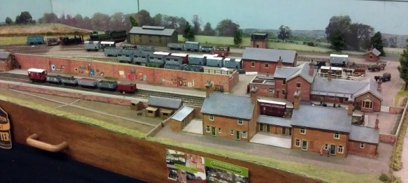
Barton Hill
2mm/N Gauge layout built by Stan Potter from Swindon.
The layout is compact without losing the sense of a much larger railway; it reflects the EWS depot at Barton Hill as seen a few years ago.
The backdrop was also nicely painted giving sense of realism with a cloudy sky, typical for the UK.
Botleigh Old North Raod
4mm/00 Gauge layout built by Ian Corps of the Southampton Model Railway Society.
This is a fictitious engine shed on the Southern Region set in the 1960s.
Brighton East
4mm/EM Gauge layout built by David Smith from the South Hants Model Railway Club.
EM Gauge stands for Eighteen Millimeters. Although the scale is 4mm to a foot (1:76), the same as traditional OO, the spacing of the rails has been increased to 18.2 mm (0.717 in). This is an accurate representation rather than the OO track at 16.5 mm (0.65 in). The reason for this dates back to the early 1930s when manufactures had trouble fitting electric motors in small steam engines in the popular, now called HO, 3.5 mm to a foot (1:87). The manufactures increased the model scale to 4mm to a foot but left the track gauge at 16.5 mm (0.65 in) and OO was born.
The layout is set between 1998 and 2003 on a Southern Region rail terminus.
The hospital in the background is having some work done and the modeling of the scaffolding was a great detail.
Right at the front of the layout was a construction site scene which was also very nicely modeled.
Fairhaven
7mm/O Gauge layout built by Fareham & District Model Railway Club.
This layout is again set in the Southern Region and depicts a through station with a goods yard.
As well as very well modeled track work and scenery the attention to lighting nicely finishes the layout. The gentle glow coming from the signal box was very believable.
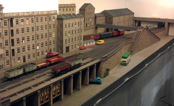
Hebble Vale Goods
4mm/EM Gauge layout built by Karl Crowther form Chitheroe.
This layout is also an EM layout so all the track had to be hand-built as well as all the rolling stock requiring wider wheel sets. I think the extra work was well worth it as this layout was superbly finished.
All the stone work was wonderfully done, I could not see any repetition in the stone pattern suggesting that commercially available wall panels hadn’t been used, neither could I see any joints. If there were any joints they were very well hidden.
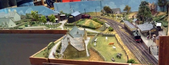
Hollow Fosse
3mm / TT Gauge layout built by John Thomas from Cirencester.
This layout set in a fictions setting in the South-West Cotswolds represents a small rural branch line in the late 1950s and early 1960s. I particularly liked the track layout, it was very different for an exhibition layout.
Everything on the layout was scratchbuilt, although it was hard to see, all the tiles on the roofs of the buildings were hand laid, one at a time.
Leicester South GC
4mm / OO Gauge layout built by the Shipley Model Railway Society.
This was a big layout and was a big crowd pleaser with lots of trains running up and down the main line as will as in the big yard.
It is set between 1948 and 1963 and is modeled on an actual location a few hundred yards south of Leicester Central Station.
An interesting feature on the layout was the large goods warehous; not only was it a fantastic model but the tracks around it all worked.
Normally working tracks is not such a big thing but in this instance the builders had managed to model a working section where, in real life, box vans full of goods would have been moved by hand using pinch bars and the small turntables you can see in the photo below.
And to show you this working here is a video of a box van being moved from the back track to one of the front tracks.
As this was a big layout it needed a big yard, and as with all the trackwork in the front, all the trackwork in the yard was handlaid.
Here is a video of a passenger train leaving and a freight train entering the yard.
Another clever section of this layout was the engine shed link. As well as the main lines and yard there was another through track that in real life connects the engine facilities with the Lester Central Station where express engines were often changed, so on this layout locomotives running light would often trundle through.
Here is one more video of nice long trains running on this layout.
Littlebridge
7mm / O Gauge layout built by Norman Cronan from the Southampton Model Railway Society.
This fictional layout is set in the West Country and depicts a branch line in the 1950s to 1960s.
Lowe Quay
4mm / OO Gauge layout built by the Southampton Model Railway Society.
This layout represents a goods yard somewhere in the West of London in the 1950s and early 1960s.
The high line at the rear of the layout carried the local electric suburban trains that you can just see disappearing in the photo below.
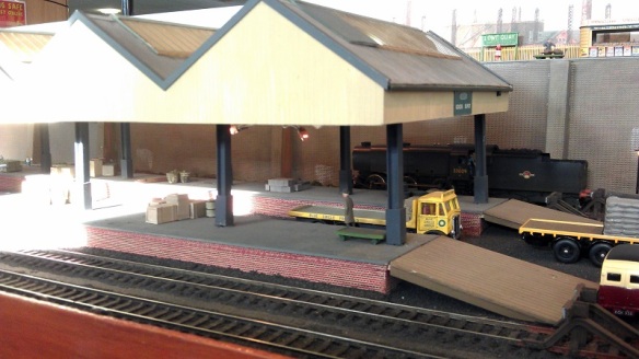
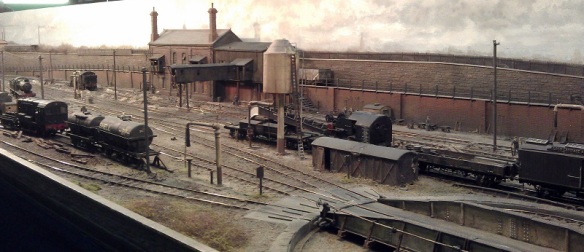
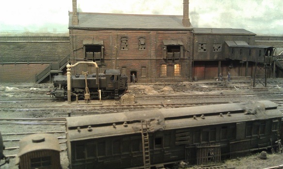
Maindee East Shed
4mm / P4 Gauge layout built by Steffan Lewis from Barry, Glamorgan.
This layout was my favorite of the show, it was simply wonderful.
It is set in 1961 at Maindee East service area in Newport, South Wales.
The level of detail on the whole layout was amazing and it was finished off with a fantastic painted backdrop showing a really overcast cloudy day.
The layout also had its own lighting which helped create the gloomy effects.
Having worked on real steam engines I can confirm the level of dirt that comes with them and this layout has captured that perfectly.
And as it is set in 1961, when steam was approaching its zenith, the engines would have been worked hard and not cleaned as preserved locomotives are today.
This layout is P4 Gauge. It stands for Protofour and has a track gauge of 18.83 mm (0.741 in). Like EM Gauge, it is at a scale of 4mm to the foot (1:76). P4 is currently the most accurate fine scale for 4mm to the foot (1:76).
The layout also featured an integral smoke system which releases smoke all over the layout depending on where locomotive are at the time; sadly I was so mesmerised with the effect I forgot to take any pictures.
The painted backdrop also gave a great sence of depth to the scene.
Even the brambles and weeds encroaching on the edges of the site are fantasticly modeled.
The coal shoot at the back of the layout certainly looks like it has seen better days but the lights in the lower room really help bring it to life.
Masham
3mm Finescale/14.2mm Gauge layout built by Peter White from Salisbury.
This layout, similar to the EM layouts, is based on the TT Scale but with a correctly spaced track gauge of 14.2mm. With a scale like this everything has to be handmade.
The layout is set in Masham which lies in the lower reaches of Wensleydale in North Yorkshire. The scene is set in 1922.
Modbury Torr
3mm/TT Gauge layout built by Paul Hopkins.
This layout represents the proposed terminal of the Great Western Railway as it would have been at the end of the Yealmpton branch in South Devon.
Priors End
4mm/OO Gauge layout built by John Smerdon from Tadley.
This layout is a fictional terminal on the Southern Region set in the 1970s.
Tal-Coed
4mm/OO9 Gauge layout built by Chris Ford from Lewes.
The layout was built in a hurry to fill an exhibition space but was very nicely done. It is set in North Wales and influenced by the Tal-y-llyn and Ffestiniog railways.
Valencia
4mm/21mm Gauge layout built by Andy Cundick from Pewsey.
This layout was is set in County Kerry, Ireland. It depicts the end terminus of the line from Farranfore on the Mallow to Tralee. It was said to be the westernmost railhead in Europe. Although the scale is 4mm, the track gauge is 21mm because Ireland run on a broader gauge railway; theirs is 5′ 3″ instead of 4′ 8″1/2.
Wadebridge
4mm/N Gauge layout built by Salisbury & South Wilts Railway Society.
This layout is set in North Cornwall between 1955 and 1959.
Wherewithial Quay
4mm/009 Scale layout built by John Bruce from Ludgershall.
This layout had to be the smallest here. It measures 21″ by 18″. But it didn’t lack in anything for its size. The scene is set in Southern Cornwall and was built as a shunting (switching) puzzle. The operator has a set of cards which are shuffled, one is picked and the operator has to arrange the wagons in the correct order shown on the card. Then another card is picked and the wagons are re-sorted. It sounds easy but when space is limited it can be a bit tricky.
Yes Tor Junction
7mm Finescale/32mm Gauge layout built by Graham Hatton from Eastleigh.
This huge layout is O scale but again with the correctly spaced track gauge of 32mm. Once again this means all the track had to be handmade and the rolling stock had to have wider wheel sets fitted.
The actual station is fictious but the viaduct is modeled on a real one although at two-thirds the size, the viaduct is now a cycle way.
Here is a short video of a medical train rushing on with supplies after a quick stop at the station.
This lovely layout was very popular but I did manage to get a videos with something crossing that huge viaduct.
And lastly I want to give thanks to my friends at Model Railway Solutions (the baseboard people) for letting me use their stand throughout the day. Here is a short video of part of their display stand showing one of their helixes for N scale. This video has not been speeded up either, that poor little class 33 diesel was zooming up and down all weekend!
In next week’s post I will be getting back to the drawing board, well mouse and keyboard, and showing you the designs for my next big N Scale locomotive which will be coming out in a few months.


 And then below is a rendering showing the main parts in the correct place.


 There is still a lot of detail to add and finish off before it is ready to go for a test print but I am hopeful that this will happen by the end of February. As with my previous locomotive models the C-855 will have brass Additions which will include the handrails and roof walks as well as several other small details. The large sandboxs on the sides will also be separate parts to make painting an easier job. The shells for both the A and B unit will be available and both will fit onto an extended Con-Cor 4500 Gas Turbine/U50 chassis. I will also be making a dummy chassis available for each unit.
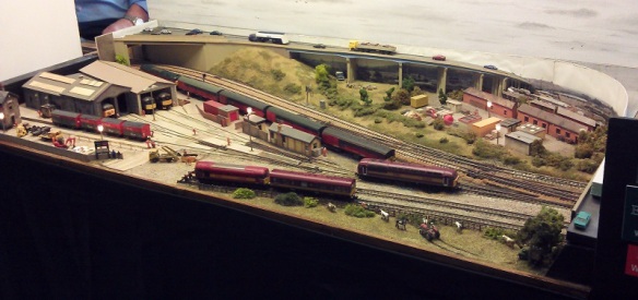


 This layout is also an EM layout so all the track had to be hand-built as well as all the rolling stock requiring wider wheel sets. I think the extra work was well worth it as this layout was superbly finished.


 Everything on the layout was scratchbuilt, although it was hard to see, all the tiles on the roofs of the buildings were hand laid, one at a time.

 This was a big layout and was a big crowd pleaser with lots of trains running up and down the main line as will as in the big yard.


 And to show you this working here is a video of a box van being moved from the back track to one of the front tracks.


 Masham


 And lastly I want to give thanks to my friends at
You must be logged in to post a comment.