The Wrenn Locomotives, despite being much older than most things you can get today, are still great locos and normally great performers. They are not easy to convert to DCC but it can be done and I’ve previously written about the 3D printed sleeves I produce to allow you to do this. But I sometimes get questions from customers who’ve done the conversions themselves, with my sleeves, and the loco runs very poorly even though it ran well on DC. In this week’s post, I’ll show you what the most common reason for this is.
Coincidently this week I’ve had two Wrenn locomotives in for DCC fitting so I can use them to point out the issue. The two locos, as you can see below, are a former LMS Duchess 4-6-2 and GWR Castle 4-6-0.


As well as being very different models visually they are different mechanically as well; the Duchess chassis at the back has a vertical motor and I covered the DCC installation procedure for this here. The Castle has the horizontal motor and that was covered here.

Before I go any further I should point out one other issue which can cause problems with DCC fitting these locomotives and that is the current draw. Sometimes older motors, and worn-out motors, can draw lots more current than intended and the DCC decoder can’t handle it. To find out what the amperage draw is for a locomotive a stall test should be done. You can read how to do this here. Both of these locomotives had a stall current of less than 1 amp, so they are ideal for DCC fitting.
So what is the main cause of problems with these? Starting with the Duchess below you can see I’ve cut off the wires as per the DCC install instructions. Both motor brushers are still fitted and you can see them touching the collector on the armature. The left brush holder, which is at the front of the locomotive, is isolated from the chassis, and the right, or rear one, is not. The problem is often that the left/front brush isn’t totally isolated. The brush still fits inside a brass sleeve which is wrapped in a rubbery paper-type material to create the isolation. Over time, remember I said these were old, this material breaks down. It’s possible heat from excessive running has affected it as well. The material hasn’t totally disappeared and it’s not a dead short, otherwise the loco wouldn’t run at all, but a very tiny intermittent electrical short happens between the brass sleeve and the chassis. Running the locomotive on DC doesn’t really affect it too much. Although it’s not good for the controller, the tiny short will affect the running, but the controller is able to push more amps through the motor to compensate. But under DCC, the decoders are much more sensitive to shorts and are not capable of delivering as many amps. The result is the locomotive runs very slowly or has no pulling power.

To check to see if this is going to be a problem remove the brush cap, spring, and brush from the left/front sleeve and inspect the insulation.

If it appears to be okay, basically not falling out, an electrical test with a multimeter can be done. A continuity test, setting the multimeter to the symbol shown below, will check to see if there’s an electrical connection between the meter probes.

With the brush removed and the brush cap replaced, check to see if there’s anything between the two brushes. This doesn’t work with both of the brushes fitted, as there’s a connection through the motor. If, when performing the test, the multimeter gives the slightest suggestion that there’s a tiny connection there, it will cause a problem.

The solution for this is to remove the brass sleeve and isolating material and fit a 3D printed sleeve to the left/front as well as to the right/rear. As the new sleeves are plastic you are guaranteed to have no short. The customer’s Duchess above is actually in very good condition and is perfect with no sign of a short, so I won’t change the front sleeve, but once the decoder is fitted, if there’s an issue it will be changed.
The Castle with the horizontal motor can suffer from the same thing although it’s not so common. Both motor brush holders are at the back on either side of the motor. Again I’ve cut the existing wires off but left the heavy gauge wire on the right, which runs from the connecting point to the brass sleeve on the right. This is because it’s a better connection than relying on the spring to deliver the power. The right-hand sleeve has the isolating material.

To remove the brush simply pull back the spring and it will slide off and the brush should fall out.

You can then do the same test as shown below.

I originally supplied my Wrenn DCC conversion sleeves in pairs to provide a spare incase something went wrong and one broke, but in hindsight I see it was a good idea as you may need to change both. The sets I sell are:
Two Wrenn horizontal motor isolating sleeves.
Four Wrenn horizontal motor isolating sleeves.
Two Wrenn Vertical motor isolating sleeves.
Four Wrenn Vertical motor isolating sleeves.
Two Wrenn Vertical & two horizontal motor isolating sleeves.
This vertical motor design was also used in the Hornby Dublo locomotives, 2 and 3 rail, so should you wish to convert any of the locomotives to DCC or repair a DC locomotive which is shorting, the 3D printed sleeves will work.


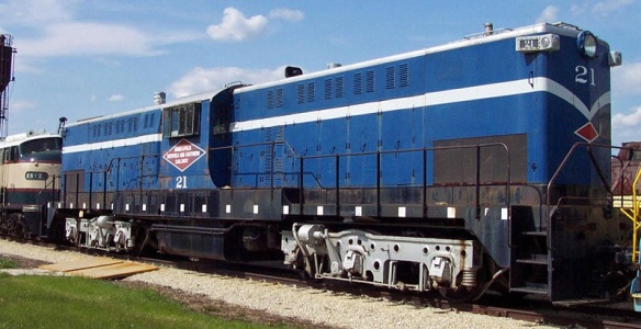 And Peabody Coal Railroad’s locomotives. (Picture from Railrpictures.net)


You must be logged in to post a comment.