This week I’ve been looking at ways to improve upon the progress I’ve made with the Baldwin DT6-6-2000 HO Scale body shell. With the main bodywork done, it’s attention to all the little details which will greatly improve the model, making them as best as they can be for HO scale.
This particular model is based on Santa Fe’s 2602 as pictured below; this is the N Scale version built by Dirk Jan Blikkendaal.
The 2602 had two single horns which I 3D printed as part of the shell, however several people used the kit to represent other railroads’ DT6-6-2000s with different horns. So I’ve made the horns separate. I intend to provide a choice of horns that will fit into the same mounting holes. This will also make them less susceptible to damage before the model is finished and on the railroad.
For the headlight, I looked at several different ways but I’ve decided to use a simple 3mm warm white LED. I’ve recessed the headlight surround to allow for a clear lens with a diameter of 4.5mm to be fitted if required.
Inside the headlight, I’ve designed the right shape to receive the LED from inside the shell.
With the LED fitted in as far as it will go, and with the flat spot indicating the negative connection at the top, the front of the LED will be in the right place to allow a lens to be fitted. My only concern is the light will also travel through the body as the material is translucent. So it will be important to paint the inside of the model and inside the headlight with a matt black prior to fitting the LED. I do this on my other N scale locos as well.
The last detail, for this week, is the windscreen wipers in the main windows. On the real locomotive these are very small but so are the windows. In order to model these in HO Scale, they will need to be etched in brass.
The actual wiper will be a simple shape with a triangular stop to prevent it from sliding too far into the locating hole.
To ensure the wiper will be in the right place and securely mounted, the locating hole is rotated to the right angle.
I still have a few details that I want to improve or add, but then I think the model will be ready for a test print. But for now, here’s how it looks.
The Baldwin RT-624, which is the successor to the DT6-6-2000, will also be getting these updates and improvements once I know they work. The 3D printed parts for the trucks and gears from my earlier post are nearly ready and hopefully will be sent out later this week. I’m looking forward to testing them and getting the right trucks on the chassis which I will share with you as soon as I can.
This week I’ve some more progress to share with you on my HO scale DT6-6-2000 project. I’ve been making lots of small changes, many internally which are hard to see, but also several to the exterior.
The body shell model, as shown below, now has all of its brass handrails positioned, along with their corresponding locating holes. Unlike the N Scale version, I will only be producing brass handrails for this locomotive because a 3D printed set, at the correct scale thickness, will simply be too weak and they’ll break very easily. The brass will be strong and when fixed into the mounting holes should stand up to the little knocks and bumps all of our trains accidentally get.
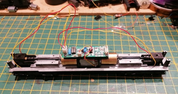
Last week I left you with my idea of adding the Preci Models DCC auto uncouplers directly to the locomotive. To make that work, I needed to figure out the connection between the chassis and the body shell, then how to mount the Preci motor.
Because DT6-6-2000 is longer than the donor C-630 chassis the coupling is moved forward, allowing the original coupling mount hole to be used only as a body shell fixing. As you can see below, with half the body shell hidden, I’ve created a hole in the body shell above the chassis hole along with a cutout for an M3 nut. The nut will drop into the cutout becoming captured and can be glued in place.
Then an M3 bolt can be used to secure the body shell to the chassis. Because the chassis tab with the hole fits into a recess in the body shell, both will be in the right place.
With the body shell secured, and without the need to modify the chassis, I can now look at the couplers and the Preci motor. The Preci motor can be mounted in many ways but normally it’s glued to the back of the Kedee coupling as shown below. (Pictures from http://www.precimodels.com). This allows the actuating string to run parallel to the coupling to give a straight pull.
With anything like this, my first step is always to model in the parts, so here is the Preci motor.
Using the model I can then accurately position the motor, and, as you can see below, there’s not enough room between the coupling and the chassis to mount it. I also find mounting the motor like this can be rather fiddly as you need to glue it in just the right place.
My solution is to mount the motor vertically in a 3D printed hole. This has the advantage of correctly locating the motor horizontally and vertically. The large hole doesn’t go all the way through, creating a pocket for the motor to sit in.
The motor would be fitted before the body shell is bolted on top of the chassis.
The space between the coupling and chassis is still tight, but as the rotating part of the motor is so small and will only have a thin string attached to it, there should be room. Connecting the string should also be done before the chassis bolt is fitted for ease of access.
With a bit of luck, and mostly modeling time, I’m hoping to have the body shell modifications done by next week. I also intend to make the horns separate parts to allow different horns to be fitted, which was a recommendation from a fellow modeler. Currently, as shown below, the horns are 3D printed directly onto the shell.
I’ll also be adding brass windscreen wipers, a cab interior and routing for wires to give cab lights. The N scale version had provision to add working headlights, but due to the size constraints, the marking/number board lights on the noses were not illuminated. But I’m considering this for the HO version. They will still be small but it’s not impossible. I’ill share my progress with you next week.
In last week’s post, I promised to share some progress with my HO Scale Baldwin DT6-6-2000 body shell and, so far, things have gone well.
The locomotive body, as pictured below, was originally drawn for my N Scale model which can be found here. This means the bulk of the drawing work has already been done.
However, as this new model will be for HO scale, roughly twice the size, some of the details can be improved or enhanced.
There’s also scope for removing material from the shell to potentially reduce the overall cost. What I mean by this is reducing the wall thickness of the model. For example, the 3D printer I use to make my shells can print a rectangle of plastic which is only 0.6 mm thick, and when this is scaled for N scale at 1:160 the plastic translates to 96mm thick. So I designed the sides etc. of the shell to be about 96mm thick, but when this is printed at HO scale, which is 1:87, they come out at 1.10mm thick, which is almost twice as thick as it needs to be. Previously I would work through the model and thin all the walls down; I used to do that for other HO models as the price of the 3D print was based on the volume of material used. However, the method of calculating the cost has changed and there are some different rules depending on the print size. One is to do with the space the print takes up in the printer, or ‘Machine Space’, and as this is a fairly large print it’s calculated that way and a small change in the volume has no effect. A big change in volume, such as the shell being solid, would mean the volume would be used to calculate the cost and it would be higher. But for us it’s ‘Machine Space’, so I can leave the bulk of the walls as they are.
There’s also the issue of strength. The bigger a section of ‘Wall’ is, such as the side of a shell, the more flexible it will become. By increasing the thickness, the ‘Wall’ section will become more rigid and overall the shell will become stronger. Considering this is an HO locomotive and the couplings are attached to the shell and not the chassis, I want it to be strong to withstand the impact and pulling forces of a heavy train. So leaving the walls thicker is an advantage.
Getting back to the details, in the last post I showed the shell split in half with the chassis fitted inside, and I needed to connect the two together.
By increasing the material behind the coupler pocket I’m able to create an area for the chassis lug to fit into. The chassis is shown in gray.
As you can see below the chassis lug has a hole in it which is 3.5mm in diameter so I’ll probably use a bolt to hold the chassis to the shell. I can indent a hexagonal hole in the top of this new section so the bolt nut becomes captured and unable to turn. It could even be glued in so the bolt can easily be tightened from below. With one at each end, this will be sufficient to hold both parts together allowing the locomotive to be picked up from the body shell.
At each end, and on either side, the original DT6-6-2000 has air vents close to the walkway. On the N Scale version, these were simply reproduced by recessing the shell to show the steel frame and the mesh, as shown below.
But for the HO version, I’ve removed the material to allow an etched brass mesh to be placed behind the frame. This etched part will be on the ‘Brass Additions’ for this model so it only needs to be fitted. The inside of the shell will be recessed for the mesh so the position will be correct, and it won’t catch on the chassis.
I’ll also be adding other etched brass parts to this model such as grab irons. The N scale version had the grab irons molded as part of the shell but the HO version will have the mounting holes only, as shown below, 3D printed into the shell.
The etched brass handrails and grab irons will be made from 0.5mm brass and will have locating holes for easy and accurate assembly.
I have more details to improve and add over the next week, but something that only occurred to me today, and which I’ve decided to add, is the ability to add Preci Models DCC auto uncouplers directly to the locomotive. Preci Models make a kit to automate a Kadee coupling, allowing it to be opened and closed via the DCC decoder as demonstrated in the video below.
I’ve fitted several of these to HO and OO locomotives with great results, but each time I had to modify the chassis or truck to mount the motor and it took a lot of fine-tuning. I had particular trouble with HO locomotives such as the EMD GP7 and F7 because the truck is very close to the pilot, which doesn’t allow room to mount the motor. But the DT6-6-2000 has plenty of room and I can design a pocket for the motor and a route for the actuating string. This will not be a requirement but a great addition, as it will allow the locomotive to uncouple anywhere on the layout. And as the DT6-6-2000 was designed as a transfer locomotive from railyard to railyard, this is ideal.
This is the perfect stage to add details and parts to the model. Does anybody have anything else they would like to see added to the HO DT6-6-2000, or RT-624 which will be following right behind, either 3D printed or in etched brass? Please use the contacts page to let me know.
Next week I’ll have more progress on the shell to share with you and hopefully my solution for mounting the Preci Models uncoupler.
In last week’s post, I shared with you the first steps in the HO Baldwin DT6-6-2000 project and I ended with the image below showing my 3D model of the truck centers which hold the gears in place. You can find the post here. The reason for modeling the truck centers was to allow me to work out how to reposition the gears to allow the axels to be positioned differently. The trucks are asymmetric and I need them the other way around.
In this week’s post, I’ll share with you my solution to solve the issue.
Inside the truck centers, in the original configuration, are 5 gears, as shown below. The green gear at the top connects to the worm gear at the end of the drive shaft. This drives the large blue gear which turns the center and right axels, shown in black. The center axel then transfers the rotation through the three red smaller gears to the left axel.
Because I need to move the center axel to the left, the gearing will need to be rearranged and ideally, reusing the same gears would make sense, but that wasn’t possible as you can see below. By swapping the red and blue gears over, all the axels are connected but there’s a big gap between the green gear and the red, so another gear needs to be added in. The purple gear is the same size as the red. But this configuration has another issue in that the blue gear is too big for space. Looking at the outline of the truck center you can see the shape was tapered above the blue gear’s original position and that would not be possible in the new location. The part would either become too thin and weak or project up and hit the chassis.
So, as an extra gear was unavoidable, I decided to make four extra gears, as shown below, and remove the blue gear completely. The four new purple gears are all the same as the red ones. To allow space for the new configuration of the red gears, the top of the truck center will also need to be extended, but that’s okay as there’s room between the truck center and the chassis.
Both sides of the truck chassis can now be properly drawn with the new gear holes set out.
The four new gears have been modeled inside a cage to make them one printed part, even though they don’t actually touch the cage. This reduces the cost of the 3D print. These parts will be test printed in Shapeways Smooth Fine Detail Plastic material for accuracy.
As well as the trucks I also had to model the Bowser chassis to see if it needed to be modified in any way to fit inside the shell. The green section is the existing circuit board, with an 8 pin DCC socket. The black section is the motor with its two brass flywheels. Everything else is metal.
The shell, taken directly from my N Scale version looks like this. I’ll be refining some of the details as they don’t need to be so big for HO, and replacing some with brass parts, such as the grab irons. I’ll also be making the grills at the bottom of each nose section from a fine brass mesh.
With the shell split in half you can see the chassis inside and it’s a good fit, with nothing requiring modification on the chassis. As the DT6-6-2000 is longer than the original body shell for this chassis I can update the new shell to utilize the original shell and fixing points.
Next week I’ll have some progress on the shell to update you with and once the test truck arrives I’ll share that as well.
Ever since I released my N scale kit for the DT6-6-2000 in 2014 I’ve been planning to release it in HO scale. The project has had a few challenges getting started but finally, it’s underway. And the first place to start is the chassis.
As with the N Scale version, I’ll be using a ready-to-run chassis to make things easier, and more reliable. I’ve chosen the Bowser Alco C628/C630. It comes with a big central motor, two flywheels and lots of weight, which will be ideal for a model of a DT6-6-2000. It also has a circuit board with a DCC socket which I also intend to use.
This particular chassis came from a Canadian Pacific C630M and has different trucks to the Commonwealth trucks used on DT6-6-2000, but when I purchased the locomotive I assumed the wheel arrangement was in the same asymmetric positions with different side frames. However, despite appearances, the wheels are evenly spaced.
But the good news is I was able to order a set of Commonwealth trucks from Bowser with the correct asymmetric wheel arrangement.
They’re a direct replacement in the chassis and now I’m at the right starting point.
The main difference between the Alco C-628/C-630 and Baldwin DT6-6-2000 chassis is the asymmetric trucks are facing the other way. With the N Scale Atlas chassis, the truck gear tower is in the middle so they can simply be fitted facing the other way. But with the Bowser trucks, the gear tower is at one end. Luckily the front and rear wheel sets are already in the right position. The DT6-6-2000 has an overall wheelbase of 54’9″, as you can see in this original blueprint below. (Clicking on the image will make it bigger).
Converting that to Metric and HO scale works out at 191.8mm which is exactly the wheelbase the new chassis has, so it’s all good apart from the fact that the center wheel is in the wrong place.
The good news is the truck side frames are separate from the truck centers which hold the gears in place.
My plan is to 3D print some new truck centers with different gear spacing allowing the side frames to be refitted around the other way. I’ve already drawn the truck centers with the original gear spacings.
My next step is to work out the new gear spacings which I’ll share with you once complete. Then I can turn my attention to the 3D printed body shell.


 By increasing the material behind the coupler pocket I’m able to create an area for the chassis lug to fit into. The chassis is shown in gray.


You must be logged in to post a comment.