A Baldwin RT-624 In HO – Part 3

It’s been a few weeks since my last post partly because of work but mostly because I’ve been out enjoying the sunshine! But I’ve also put some time into finishing off the RT-624 HO project and it’s now ready for a test print.

The two versions of the Pennsylvania Railroad’s Baldwin RT-624, as shown below, are very similar but there are little differences that mark the change in the two different batches ordered.

The first depicts the original batch of fourteen units, numbered 8952 to 8965. With the exception of 8952 and 8953, they were fitted with the PRR Trainphone. This has mostly been modeled with etched brass. The item on the front, which I mistook for a bell, is actually the receiver for the Trainphone, with the antenna along the roof working as the transmitter. Thanks to Norman Bell and Gus Foster for the information.

Gus said ‘The device you were questioning on the top of the train-phone-equipped RT-624 is the train-phone receiver. These were disk-shaped devices consisting of a coil of wire that acted as a receiving antenna for the induction radio equipment used in the late 1940’s and 50’s.
As you may be aware, the train-phone system induced electromagnetic signals into the rails and the signal wires that ran parallel to the tracks. The government did not open radio communication frequencies to railroads and others until later in the 1950’s. As a result, the PRR used a radio induction communication system known as “trainphone” for communication between locomotives, cabin cars (cabooses), interlocking towers and railroad stations. The “handrail” shaped equipment on the top of diesel locomotives, cabins and tenders were the sending antennae that induced the signal out to the rails and parallel metallic conductors. The receivers picked up the signal. So to send and receive, both the antenna and receiver had to be near the location of the radio.

The receiver on my RT-624 is 3D printed but I’ve designed it to be a separate part to be fitted later as I can see it easily getting broken off during shipping.

The later batch, numbered 8113 and 8724 to 8731, had no Trainphone equipment and a lowered headlight. They also rode on General Steel Castings Delta equalized trucks as opposed to the General Steel Castings Commonwealth trucks used on the first batch. Currently I’m using Bowsers truck frames for both, along with my truck centers which are required to rotate the trucks 180°, but I’m considering offering a 3D printed set of each truck frame.

The handrail on the end is split by the fold down walkway and MU hoses. I haven’t modelled the MU hoses yet. I have the ones I did for my N scale version but they look huge in HO so I’m re-thinking that and I may make them as brass parts that clip in. The center section will be 3D printed and again it’ll be a separate part to protect it when shipping. The corner handrails will be brass and will fix through holes in the center section to ensure a strong and accurate fit.

And that’s it, the HO RT-624 is ready for a test print. I’m planning on printing the early version with the Trainphone because that one will have more things to check. While the test print is in production I’ll update the etched brass parts sheet for the different parts. Most are the same as the DT6-6-2000 but there are differences; I can’t use the same etch as one of the four main handrails is a different shape. In the image below I’ve circled the walkway which is longer, pushing the crank in the handrail further along.

Once the test print arrives, it should be easy to check it fits as I have the Bowser chassis here that I used with my HO DT6-6-2000. It will also get the powered Kadee couplings so it can be tested doing some switching and I’ll share that with you, well as long as it doesn’t continue to be sunny outside!

A Dummy Knuckle Coupler for OO Gauge – Part 3

Back in July, I shared with the second part in my design of a dummy knuckle coupler for OO gauge rolling stock.  You can find the post here.  Since then the first prints have been through several tests and they performed very well.  In this post I’ll show you the small changes I made to the design and share with you how to get some.

The original design, as shown below, was printed in both Shapeways clear Fine Detail Plastic and the Black Versatile Plastic.  The Black Versatile Plastic turned out to be so good I’ve carried on with only this material.  Not only is it strong, but as it’s already the right color, they’re ready to use.

The original design was for a dummy knuckle coupling which would work with Kadee couplings as well as each other.

The first issue I had with them, albeit a small one, was with the knuckle section.  As the actual knuckle, unlike the Kadee, doesn’t swing, and it tended to grip on tight curves.  I opened the jaws slightly to allow a bit more movement.  This solved the issue.

The second issue was due to height.  As I’ve said in other posts about couplings, despite there being the NEM standard regarding couplings and height, different manufacturers have positioned their coupling pockets at different heights. Some seem to be high and some low, which leads to the situation of an uncoupling, especially on gradients as the rolling stock crosses the transition from flat to inclined.  My first answer was to offer three different types, as shown below; high, standard and low.

However given there may be a few different lengths, this makes for a large number of different couplings to manage.

A much simpler idea was to make the knuckle 2mm bigger.   By moving the top up by 1mm and the bottom down by 1mm all versions are covered.  The wings either side of the knuckle were also removed as they performed no real purpose.

This new design was 3D printed on sprew in the Black Versatile Plastic.  The sprew helps reduce the cost of the parts.

The Bachmann OO Class 66 has, what I consider, to be a correctly positioned NEM socket, that is, it’s in the middle of all the rolling stock I’ve tested.  The new coupling fits perfectly and doesn’t look too out of place.

Compared to a standard Kadee in another Class 66, the new coupling looks okay, even if it’s a bit deeper.

The two coupled perfectly and as you can see the new coupling sticks up and down by 1mm, ideal if the coupled item of rolling stock has its NEM socket out of place.

This coupling length is based on a Kadee No. 19. which works well for most items, although I found Hornby coaches ended up with a larger gap between them than I liked, so a shorter version will be designed soon.

For now, these are available in packs of 10, 25, 50, and 150 and you can find them using the links below.

OO NEM Dummy Knuckle Coupling (Large) x10

OO NEM Dummy Knuckle Coupling (Large) x25

OO NEM Dummy Knuckle Coupling (Large) x50

OO NEM Dummy Knuckle Coupling (Large) x150

Once the length of a shorter coupling has been finalized, to reduce the gap between Hornby coaches etc, I will share this with you too.  But now it’s back to the drawing board as I have several projects to wrap up which I’ll also share with you in due course.

OO Gauge Fixed Link Wagon Couplings Revisit – Part 2

Last month I revisited my OO Gauge Fixed Link Wagon Couplings, you can find the post here, and last week the sample set arrived so now I can show you how they worked out.

The sample set, as pictured below, contained 8 couplings.  There’s a mixture of 3 Link and Instanter couplings with some being straight and some stepped.  (See the coupling page here to find out what each is for).

The biggest different to the couplers was the removal of the flexible section which was the weakest point.

To test the couplings properly I paid a visit to the McKinley Railway which uses a mixture of Kadee couplers and these 3D printed couplers for its wagons.  For the test we made up a train with a variety of couplings.

At the start we had some box vans with Kadee couplings installed.

Then we had one of the new 3D printed Instanter couplings.

Followed by a 3D printed 3 Link coupling.

And at the back were three vans connected with my 3D printed coach drawbars.  These have not been released yet so I will have more on those in a later post.

The 3D printed couplings clip directly into the NEM sockets; these box vans all have their couplings sockets at the same height so the stepped couplings are not required.

For the test the requirement was fairly simple.  Will the couplings without the flexible section allow the train to navigate corners, ‘S’ bends and junctions without pulling the box vans off the rails?  And the answer is ‘yes’, as you can see in the video below.  The train was sent all over the layout, at full speed, including passing through the yards, tight curves and junctions where speed is normally reduced.

Of course running forwards the train is being pulled but what about pushing the train?  In the video below you can see the train being propelled through a busy set of junctions at max speed, which was way too fast, with no issues right until the end when the last box van derails due to a wheel issue.  But the couplings worked.

I do need to point out that although these are much stronger than the original version they are still made from the same material and will break if over-twisted, just not so easily.

Now the new version has been tested and proven to work without the fragile flexible section I’ll work through the range and update the shop.  I’ll add a note to each relevant product to mark it as the second version but if you’re unsure if it’s been upgraded before you buy please drop me an email or get in touch via the contact page and I can check for you.

A Dummy Knuckle Coupler for OO Gauge – Part 2

Today I had a delivery from Shapeways containing some parts I’ve been waiting a while for and I thought I’d share them with you before I get a chance to really test them out fully.

As well as several other bits the package contained the two parts below.

The white jumble of parts contains many bits, from gears to couplings all on one sprew, which have been 3D printed in Shapeways Fine Detail Plastic.  The parts I’m interested in for this post are the couplings; there is a new sample set of my 3 Link and Instanter fixed couplings without the flexible section and a set of dummy Kadee couplings.

The new 3 Link and Instanter fixed couplings will be covered in a later post as they need to be tested on a OO layout and as I’m an N scaler that is a little difficult tonight but the dummy Kadees can be test fitted now.  Below you can see one next to an actual Kadee with the NEM fitting.

The dummy’s fit together well and there’s a bit of movement to allow for rotation.

They also fit well into the real Kadee.  However, they rotate well in one direction, as shown below, but in the other direction the left hand side of the dummy catches the lug designed  to hold the Kadee spring to the knuckle jaw.  This can easily be rectified by reducing the length of the left hand side.

I do have one OO Gauge loco to hand with NEM pockets and it’s a Bachmann Class 66.  The new dummy coupling clipped right into place and looks good.

As I only have the one item with NEM sockets to hand tonight I can’t do much more testing than holding the original Kadee up so you can see how well they fit.

But what about the black mesh cylinder?

This is how I 3D print my N Gauge Short Rapido Replacements in Shapeways Black Versatile Plastic; you can read about those here.  I added a few dummy Kadee couplings into the cylinder as well to see how they printed in this material.

And I must say they came out even better than expected.  They fit perfect with the Fine Detail Plastic set and the original Kadee.

Plus they also fit perfectly into the NEM socket as you can see on the class 66 below.

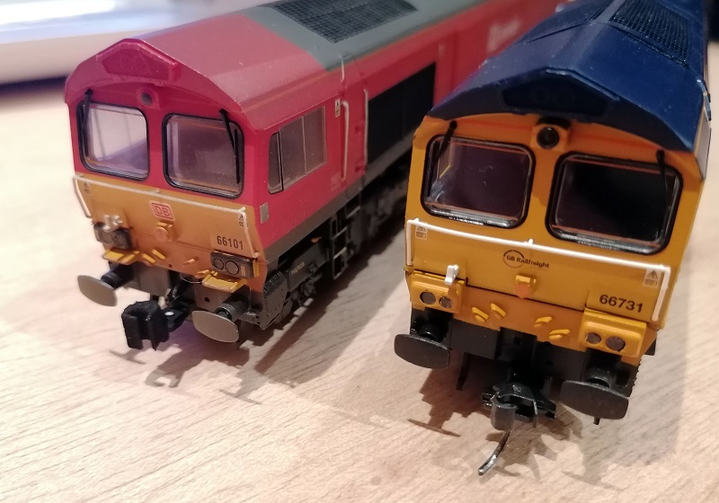
As the Black Versatile Plastic ones come pre coloured, are more flexible, strong and don’t need to be cleaned before painting I think these will be the ones to use.  But as with the new 3 Link and Instanter fixed couplings it’s now off to the actual OO railway for some proper testing before I’ll know if they really work.  I’ll let you know more when the testing is done.

OO Gauge Fixed Link Wagon Couplings Revisit – Part 1

In March of 2017 I first introduced my OO gauge fixed link couplings for UK wagons, you can find the post here, and they developed into a range of couplings to suit both 3 Link and Instanter couplings.  They’ve been doing well but there have been a few issues so a revisit to the design is required.  In this post I’ll be showing you the first steps.

The couplings, as shown below, are designed to fit into NEM standard pockets and form a permanent link between two wagons whilst retaining the look of a 3 Link and Instanter coupling.

And I think they do this very well.

At the time, an important design feature was the ability to add some flexibility onto the coupling to allow it to navigate corners.  I considered the main part of the coupling too stiff and was worried it would pull trucks off the rails on corners.  A solution was achieved through a flexible section; this was covered in the second post which can be found here.  But it’s this flexible section which has caused the issues.  The material used for the couplings is Shapeways’ Smooth Fine Detail but, as you may have read in other posts, it is brittle and the couplings tend to break at the flexible section, especially when handling several wagons joined together off the rails.  They tend to break here as it’s the part of the coupling with the least material.  One thing I also noticed is that the direction of the print also had an effect on the strength.  The original couplings were printed loose and often standing up on end.  This meant each layer of 3D printed material had a small surface area to bond with the last.  Printing the couplings laid down significantly increased this area and therefore the strength.  Since I made the alteration to print the couplings as a group, see the third post here, they’ve all been printed laid down, but they could still benefit from more strength.

As it turns out the couplings do have some flexibility and the required amount of movement is not great so I’m going to try some 3D printed couplings without the flexible section to see how they do.  Below you can see the revised couplings on the right.

The taller couplings had a much larger flexible section and coincidently it was much stronger; it was the flat coupling which broke more than any others.  But I’m going to try them all.

I’m also going to do some experiments with some of the other materials.  Once I have samples in hand I’ll share the results with you.

Alco C-855 N Scale Replacement Lifters

Sometimes trains get damaged, I’m sure it’s happened to most of us at some time.  And there’s always that one point on a model which is more prone to getting damaged than the rest.  On my C-855 shells it’s the lifters at the rear of the model.

The C-855 has four lifting points to allow the whole body to be lifted off the trucks.  There are two in the nose and two at the rear. The nose lifters can be seen below; there’s a recess behind the hole to allow a lifting shackle to be attached.

The rear lifters are raised up on posts.  This is to keep all four lifting points at the same height.  On the real locomotive the posts would have been thick heavy metal but in N Scale acrylic they’re a little thin.  And it’s these that are likely to break if the shell is dropped.

If you can find the broken part it’ll fix right back on with a drop of superglue as this material usually breaks with a clean edge.  Injection moulded parts tend to distort when they break so fixing them back on can be harder.

But if you can’t find the part a replacement is needed so I’ve created a set of four lifting posts as the C-855B has four posts because it has no nose.

The set has two left and two right hand posts and they are all 3D printed on a ring which makes them a single part and therefore cheaper to print.  I’ve made them longer than normal so they can be shortened to the right length depending on where the break is.  As the material is hard these will not cut like injection model plastic but can easily be filed or sanded to get them to the right length.

The replacement C-855 lifters can be found here.