As well as 3D printing model railway parts and kits I also build a lot of layouts for customers. Sometimes it’s a whole layout or sometimes, as in this post, I get asked to just do one bit. This week I wanted to share with you a recent job I did for a customer installing a pair of helixes in their new layout.
The customer is building a new layout in OO gauge (1:76.2) with staging yards on a lower level, 12.5″ (317.5mm) below the main baseboard, and they wanted to join both ends of the staging to the layout with a helix in each corner. Using 3rd Planit, which is 3D model railroad design software (https://www.trackplanning.com), I was able to draw out their baseboards and the track the customer had already laid in the staging yard. This allowed me to create a plan for the point work required, but most importantly shows the customer just how big the helixes were going to be.
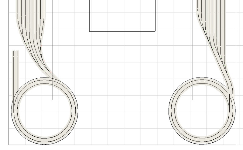
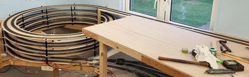
As you can see the new helixes overhang the baseboard. The outer track on each helix has a radius of 22.5″ (572mm), the inner track is 20″ (505mm). The customer was concerned about the size as they’d expected them to be a lot smaller and fit onto their baseboards, but there are several good reasons for choosing these sizes.
Firstly is the availability of helix kits. I could design my own, cutting all the material and making a truly unique helix for this build, but that is very time-consuming and therefore costly, and as there are already several great kits on the market it makes sense to use one. The kit I used for this layout came from Model Railway Solutions, they provide two sizes of helix kits for OO and this leads to the second reason.
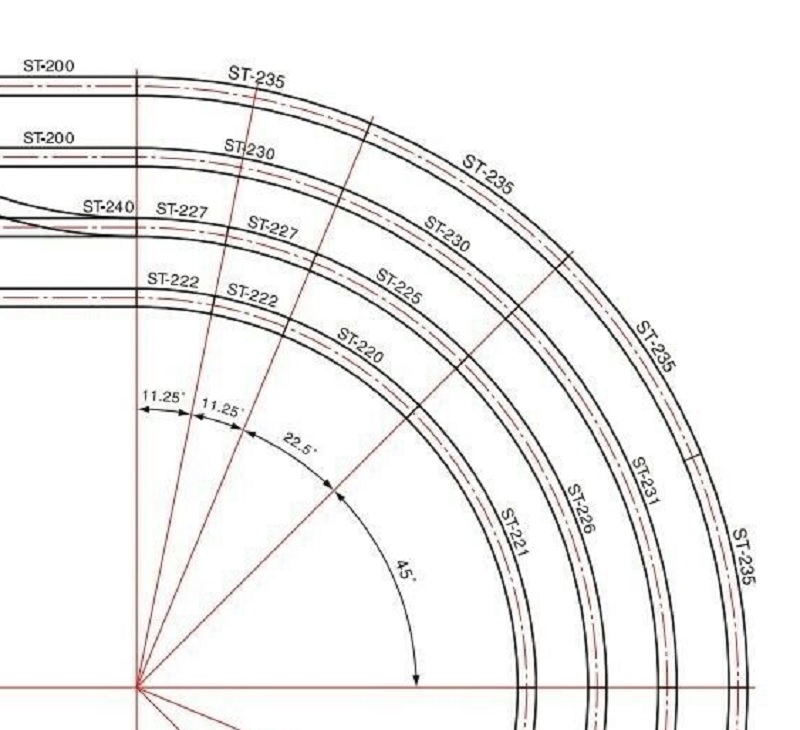
The first OO helix kit MRS produces is for 2nd & 3rd radius curves and the second kit is for 3rd & 4th radius, but what does that mean? The terms 2nd, 3rd, and 4th radius refer to the radius of Set Track, the curves often supplied with train sets, starter packs and sold separately by companies such as Hornby and Peco. Set Track is described as a range of rigid curves, straights, crossings and points (turnouts), made to the standard British geometry. With the curves, as the number gets bigger, so does the radius, and below you can see Peco’s Set Track curves from 1st to 4th radius. The key advantage is you can easily keep multiple tracks parallel around curves.
MRS’s helix kits have been specifically designed to match Set Track and for this build, I used the 3rd & 4th radius kit. But why choose that over 2nd & 3rd radius kit which would be smaller? The answer depends on what type of layout you’re building. Some larger locomotives have a minimum radius they can navigate and a few specify above the 2nd radius curve which is 17″ (438mm). So if you have large locos, which my customer does, they may struggle with the tight curves. But the main reason is the gradient.
These helix kits climb 3″ (76mm) with every revolution. As the radius increases the distance traveled increases and consequently, the gradient reduces. In the table below you can see how this works out.
| Radius | Length of Full Circle | Gradient | |
| 2nd Radius | 17″ (438mm) | 108″ (2752mm) | 2.762 % |
| 3rd Radius | 20″ (505mm) | 125″ (3174mm) | 2.395 % |
| 2nd Radius | 22.5″ (572mm) | 141.5″ (3595mm) | 2.115 % |
Although the difference in gradient may not seem a lot, it can make a huge difference to a locomotive pulling a train uphill around a curve. My customer wants to run steam locomotives pulling at least six coaches so in order to give them the best chance the largest radius is recommended.
You may have noticed from the track plan at the start that the helixes are not mirrored but both climb in a clockwise direction. This is because trains in the UK run on the left so making them climb a helix in a clockwise direction means they are going up on the larger radius which is an easier gradient and coming down on the tighter radius which is slightly steeper. Model trains tend to find it harder pulling uphill than braking downhill.
The helix kits from MRS have three main parts. An entry/exit ramp, a first-level base kit, and a riser kit. The entry and exit ramp is a tapered section that allows the helix to start on top of a flat baseboard without modification.
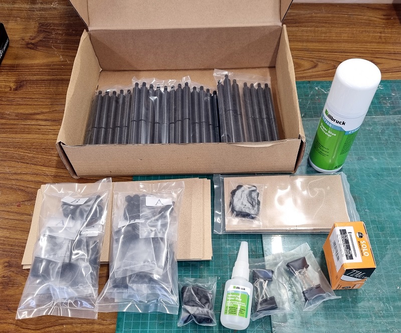
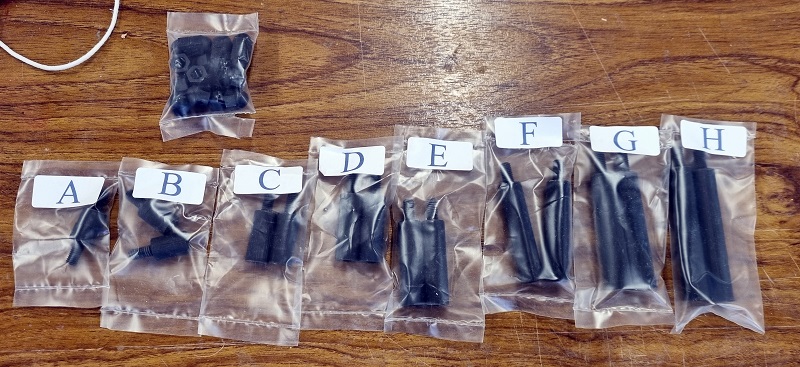
All the small bits come boxed together, the amount depends on your build. All these parts are for two helixes, each with four rotations.
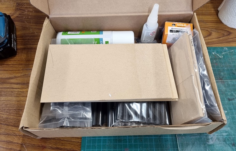
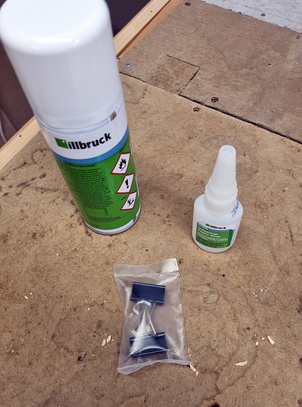
In the box, you get 3D printed pillars ranging in size for the first level base kit, regular pillars, pillar caps, clips, superglue, superglue setter & cable ties. The box of screws in the photo are not part of the helix kit, they’re for fixing down the baseboard tops.
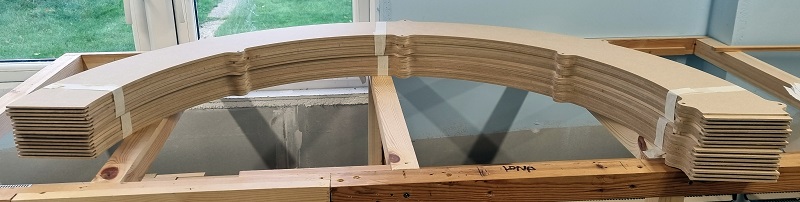
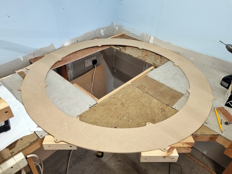
The actual helix deck is laser cut from MDF, each one has a stepped end to allow easy and accurate joining.
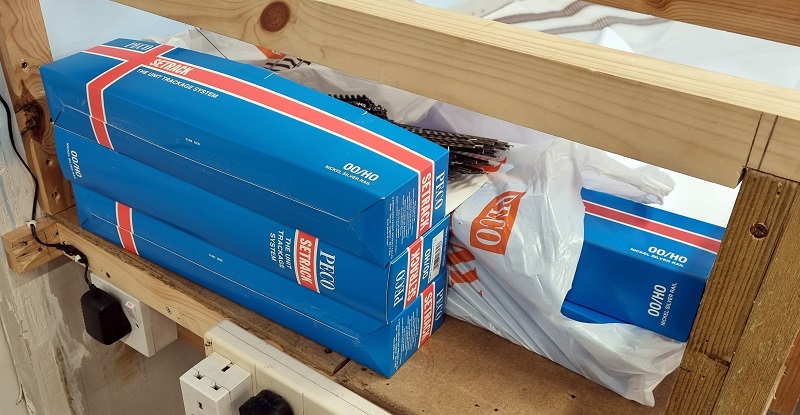
The one thing not included in the kit is the track and it’s amazing how much you need for a helix. I chose to use Peco Set Track and to build these two helixes I needed 64 3rd radius double curves and 128 4th radius curves (they don’t come in double).
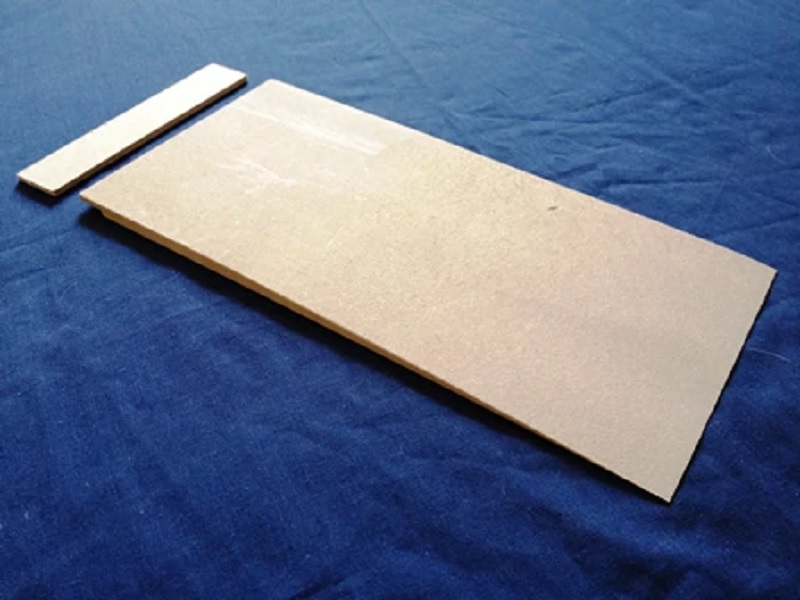
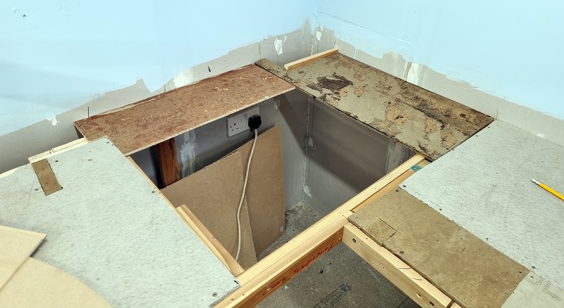
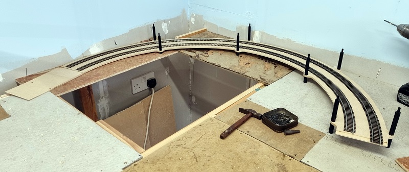
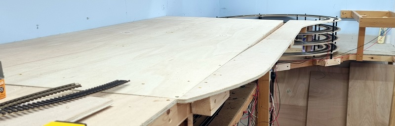
As I said at the beginning, the helixes are larger than the baseboards and although my customer had cut holes in their benchwork, extra support was going to be needed.
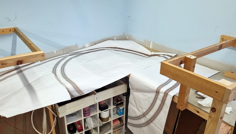
The support needs to be under the pillars of the helix and as long as it’s flat it doesn’t really matter what it’s made from. I was able to use the offcut material to make a flat surface, instead of buying new timber. The important thing to note is the hole in the middle, which is crucial as once the helix starts going in you won’t be able to reach the backtracks without it.
I added a triangular support at the front and some outcrops so each pillar has somewhere to sit.
In MRS’s first level base kit the 3D printed pillars are labeled A to H in ascending order. these sit under the helix and screw through the deck into a regular pillar. These first pillars are effectively the feet. They do have a thread in their underside should you wish to fix them down but the overall weight of the helix once complete will stop them moving.
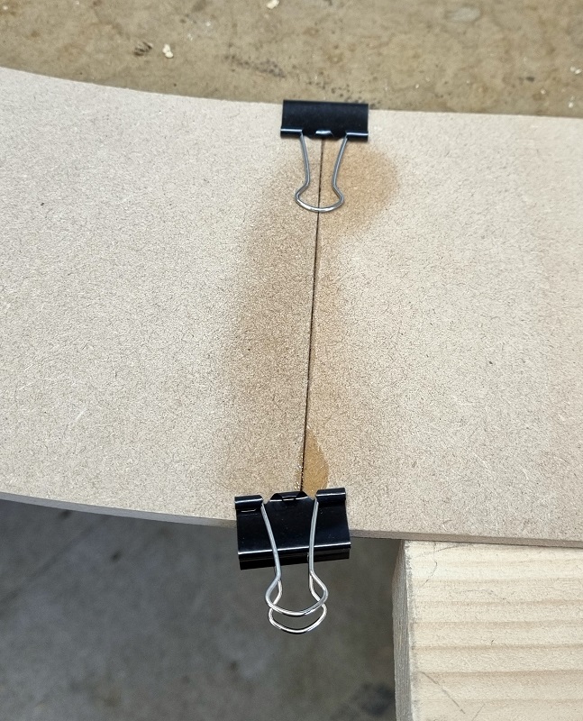
But before we start fitting these the entry/exit ramp needs to be fitted and for this, the superglue is used along with the two bulldog clips.
Because the height between the helix decks is at a premium any fixing that protrudes above or below the deck is not useful so the joints are created by gluing the steps together and holding in place with the clips. This superglue holds fast in about 10 minutes. The spray is a superglue actuator that causes it to set instantly. I used it on this first joint but as for the later connections, I found I didn’t need to. Simpy putting superglue on the step, fitting the next board, and clamping for 10 mins with the clips worked perfectly.
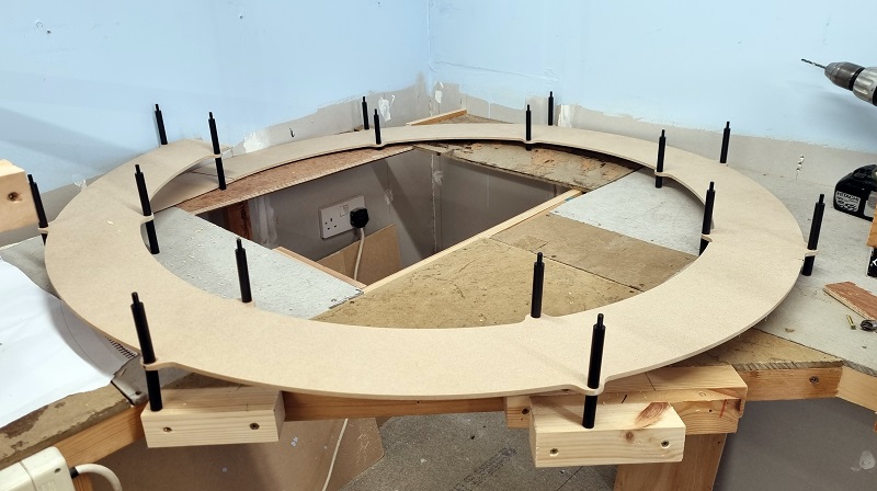
The first 3D printed pillars can now be fitted along with the standard pillars. The standard ones on top act as the nuts, fixing the lower pillars. When screwing these in don’t overtighten them. You don’t need any tools, finger-tight is sufficient.
If the pillars are sat on a flat surface, the helix will climb at a constant gradient.

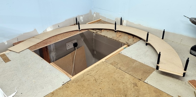
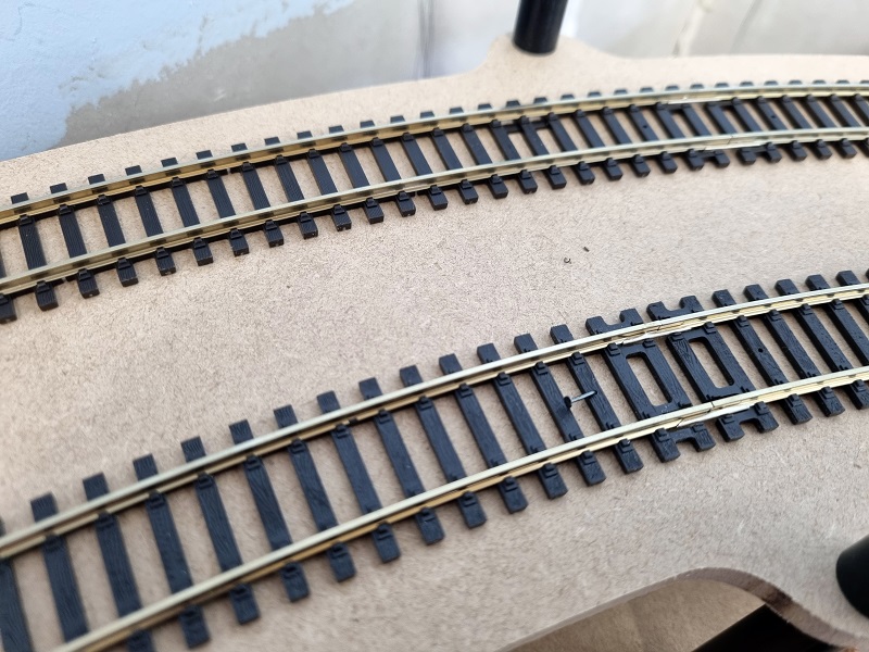
I test fitted the second deck section to make sure everything was in the right place, the end of the second deck fitted over the entry/exit ramp. Don’t fix the second section in place yet as you need to start laying the track onto the helix first.
With the helix in the right place and the second section removed, I put a few screws in the entry/exit ramp to hold it all in place, then started laying track. When using Set Track you instantly realize the benefit; it’s a perfect fit and holds a constant radius with ease.
You may have noticed I haven’t used cork or underlay under the track, this is to maximize the height between the decks. I also chose to pin the track down. Because it’s Set Track and doesn’t flex you only need a few pins, which is good because there’s some bounce if you try and pin between the pillars, but close to them it’s okay. One thing to consider is the length of the pin. The deck is only 7mm thick so if a track pin is put all the way in it’ll stick out below and I guarantee you’ll scratch the back of your hand when cleaning the lower tracks at a later date! The solution is to put the pin in only enough to hold, then bend it over as shown below. As long as the pinhead is below the top of the railhead it won’t create problems with train clearance.
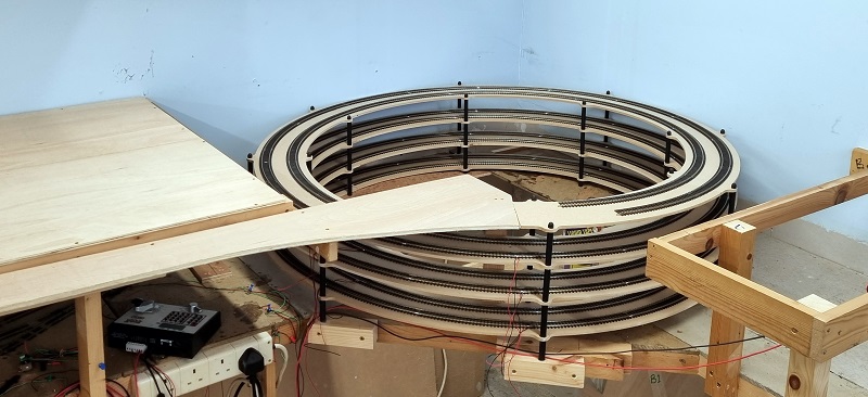
Something else to consider before you take the build too far is track power. Even on the inner line, a full loop is 125″ (3174mm) long. Times that by four rises and that’s a long way if you only have a power feed at the top or bottom of the helix; your loco may start to slow down as it gets further away from the power feed. My solution for this is to put a power feed to every level of the helix and solder the fishplates/rail joiners together for the other joints on that loop. In the photo below the power feeds are at the bottom of the photo. All the fishplates/rail joiners have been soldered with the exception of the ones at and above the entry/exit ramp.
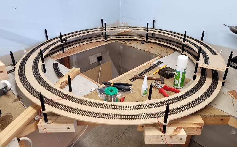
After several rotations, track laying and soldering as I go, the helix takes shape. Building from the inside is much easier, you can now see why that access hole was crucial.
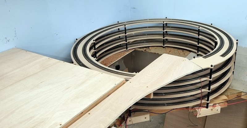
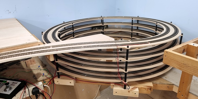
As can see above the top rotation is not a full circle, which would put the track facing the wrong way to enter the main layout, but that also means some of the elevation gain is lost. You may recall that the staging was 12.5″ (317.5mm) below the layout. The helix climbs 3″ (76mm) per revolution, so with just over three and a half it has only come up by about 11.4″ (290mm). To overcome this I build a ramp at the same gradient of the helix onto the new layout baseboards.
The track on this section will be laid with flexi track and have larger sweeping curves as it’ll be a visible section of the finished layout.
The cable ties supplied with the kit are used to hold the track feed wires together so they don’t snag on passing trains.
The helix on the other side is basically the same, although the top section is near the wall so the trains are again climbing on the outside of the helix. You can see the pillar caps holding down the top deck sections. These screw onto the pillars and act like a nut as well as covering the last of the exposed treads.
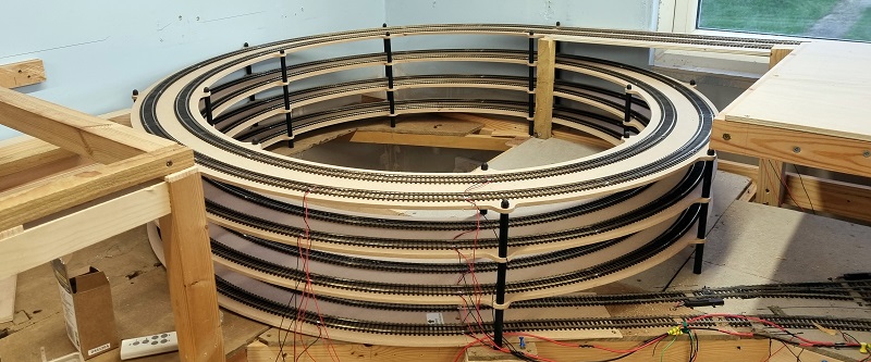
Again I constructed a ramp to make up the height difference that runs at the back of the new layout benchwork.
With all the track down and power connected, a quick test had to be done. The loco is a Heljan Class 28 Co-Bo Diesel.
These kits are a great way to add a helix to your layout and can be built in a variety of height combinations to suit your needs. They are also available from MRS for N Gauge Set Track and Kato Unitrack.
I build a lot of layouts in all shapes and sizes and I look forward to sharing some more with you in later posts.


You must be logged in to post a comment.