
One of my customers has been having some issues with his layout since switching to DCC operation; they find that trains short and stop when crossing Peco Insulfrog crossings. In this post I’ll explain why this happens and show you how I fix it.
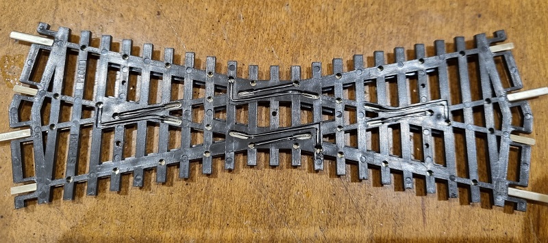
The Peco Insulfrog crossing comes in short and long versions and can be used in many ways. The term Insulfrog refers to the areas where rails cross each other, which is called a ‘frog’. An Insulfrog has a plastic separator to isolate the rails electrically. With an Insulfrog crossing, the two tracks are electrically separate from each other. So differently controlled trains can run on each line, as long as they don’t hit each other.
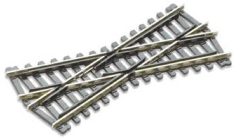
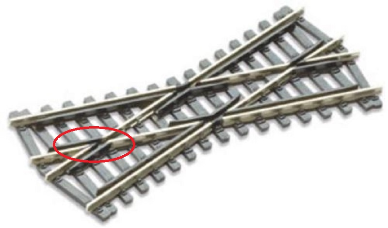
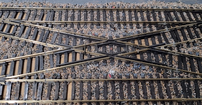
But the problem comes right at the centre of the frog where trains with wide wheels cross the plastic isolation. In the image below I’ve circled the area called the ‘frog’. The downside is here the larger the plastic frog, the bigger the dead spot is, or area without power, for the locomotives. So Peco has made it as short as possible to limit the dead spot. However, if a locomotive or regular item of rolling stock has wide metal wheels, that is, wider than the rail, the wheel will make contact with both incoming rails at the tips.
When using these on a traditional DC or Analogue layout there tends to be no issue with shorting at the frog because power is normally only given to the tracks a train is running on either by a power routing point or switch, so it’s more than likely the other track is switched off. However, with DCC all the track is powered and shorts at the frogs are very likely. This is why Electrofrogs, which means the frog is made of all metal, are ideal for DCC. But the polarity of the frog, positive or negative needs to be switched depending on the direction the train needs to travel.
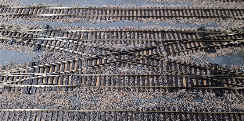
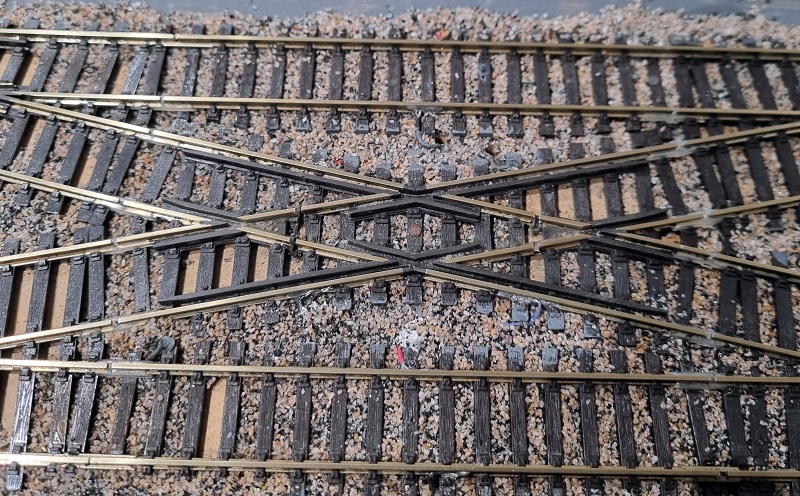
My customer has several of these crossings, the one below is at a major junction between four double slips. To solve the issue of trains shorting on this crossing I’m going to upgrade it to work like an Electrofrog crossing, just without the metal frogs.
Fortunately my customer had already installed insulating fishplates at the ends of the frogs. This is always needed with Electrofrog points, crossings and slips but not for DC/Analogue. If these were not already there I would need to cut the track using a slitting disc in a Dremel-style tool to create the gap.
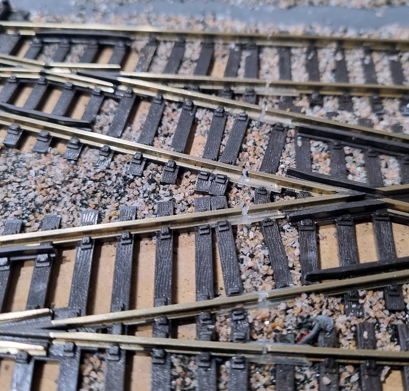
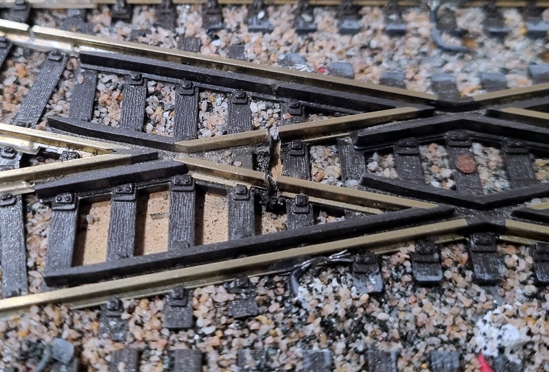
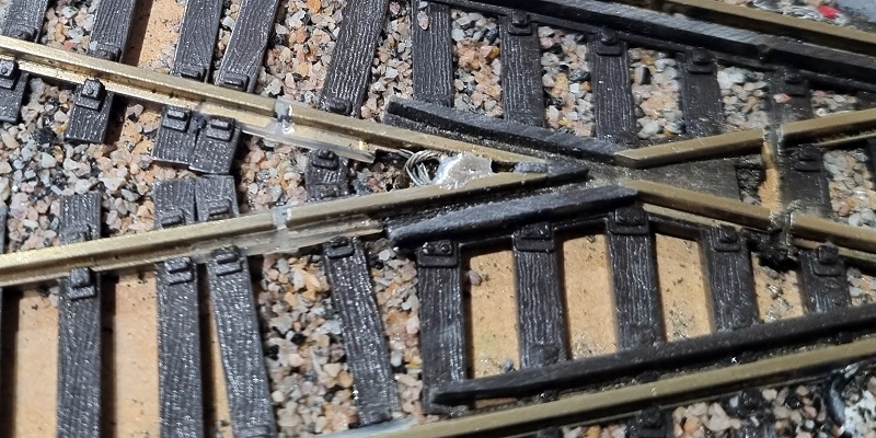
To completely isolate the frog section, I need to cut the rails on the inside of the frog as well. The cuts want to be roughy in the middle of the rails section; this is because Peco has placed a wire under the plastic frog to bridge it. You can see the bridge wires below. The cuts need to be between these wires.
Using a slitting disc in a Dremel tool I’ve cut the rail in four places, above the gap in the sleepers to help keep the integrity of the rail support.
It’s important to make sure you cut deep enough to go all the way through the metal rail.
The frog area should now be completely isolated from everything, and currently, the two frog rails are separate from each other. To get power to them, I drill a hole just outside the frog and feed a wire through, I always use green, because most frogs are green! I strip more than normal off the end of the wire and twist the strands.
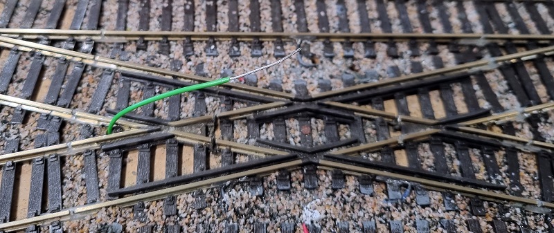
Then I loop the end, not a full 180° but to the same angle as the frog.
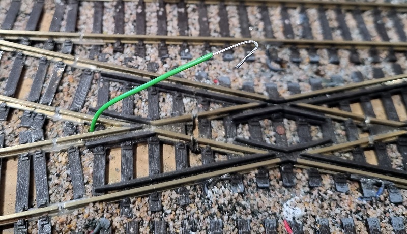
The stripped wire can then be pushed into the web of the rail which is below the railhead and out of the way of any passing trains. The wire needs to be in contact with both rails.
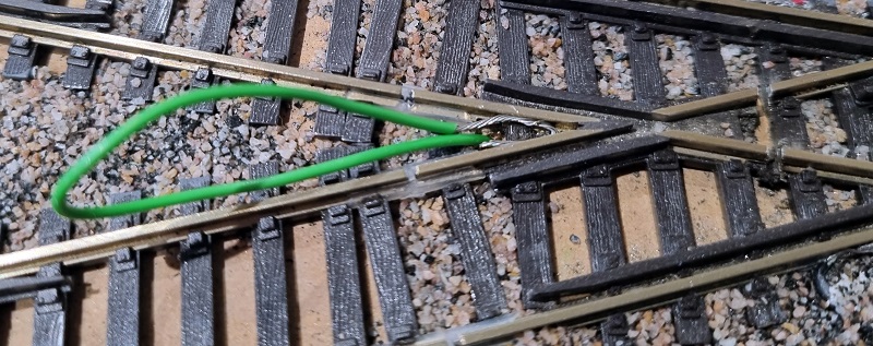
The wire can now be soldered to both rails which creates a basic Electrofrog. The excess wire is pulled back through the base board.
This is repeated on the other side of the crossing.
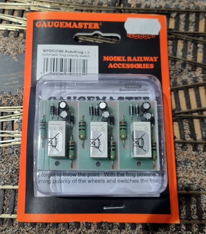
Although the frogs are now connected to a wire they will need to switch to the right power feed depending on which way a train is going. If it’s going from top left to bottom right the left frog will need to be connected to the bottom rail, but if travelling from the bottom left to top right it will be the top rail. This could be done with a manual switch but to make things easier I like to use Autofrogs. These are electronic relays or automatic frog polarity switches which detect if the frog is at the wrong supply and switch it before the DCC command station realizes there’s anything wrong.
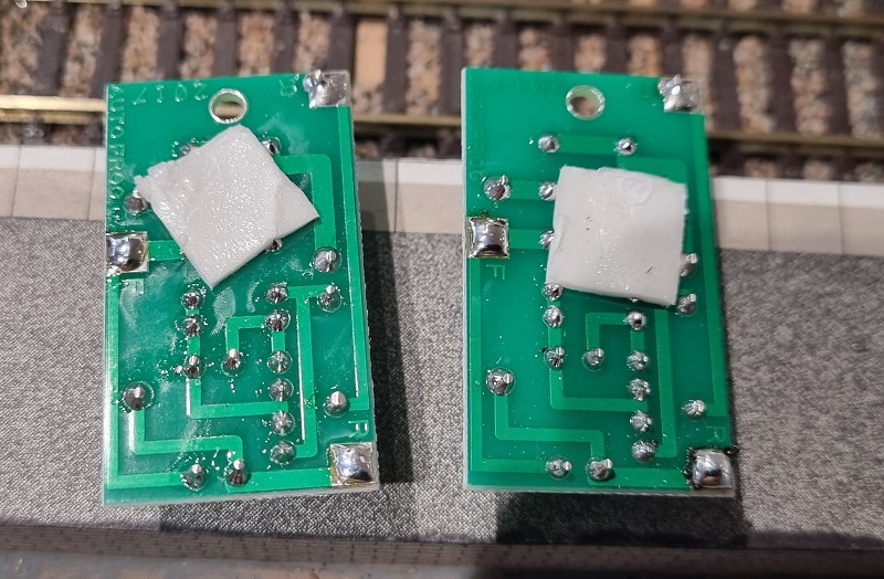
On the reverse of each one are three solder pads. The one marked F, on the left, is for the frog wire. The other two marked R, are for rail connections. It doesn’t matter which way round the DCC is connected to these pads as the Autofrog will always pick the right one itself.

I first add some solder (often called ‘tinning’) to all the pads.
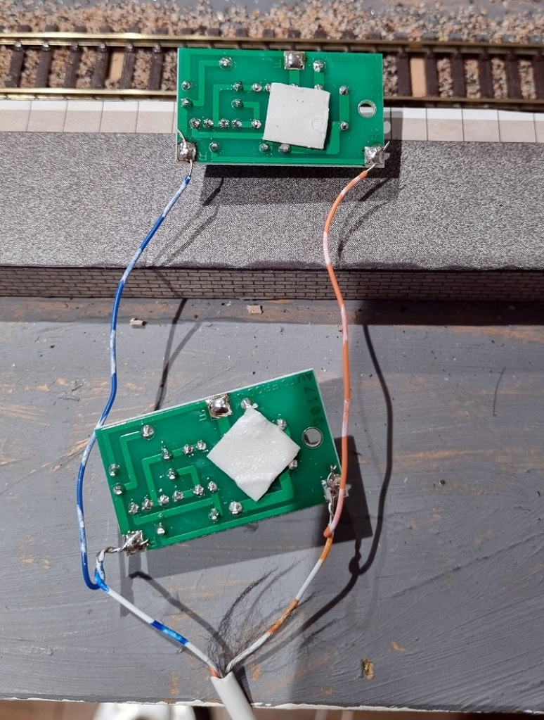
Then I connect the power cables This particular layout uses four core cables to connect power and track power to its point motors so I used the same wires.
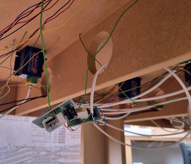
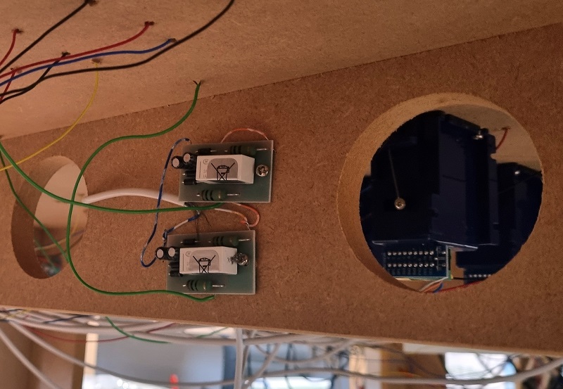
The frog wires are then connected to the Autofrogs under the layout and the four core cable is connected back to the main DCC bus.
At this stage, I run trains through the crossing to check it all works as anticipated. As a train crosses in a different direction to last time you should hear a faint click from the Autofrog as it changes the polarity, the train should carry on without even noticing. Which it did.
The last thing to do is secure the Autofrogs, and they have a single hole which can be screwed to the base board.
Doing this eliminates the shorting issues and trains now run without shorts and stalls.
The Gaugemaster Autofrogs work well but they’re not the only product that works like this. Tam Valley makes a product called a Frog Juicer which is all electronic, unlike the Autofrog which has a mechanical relay.
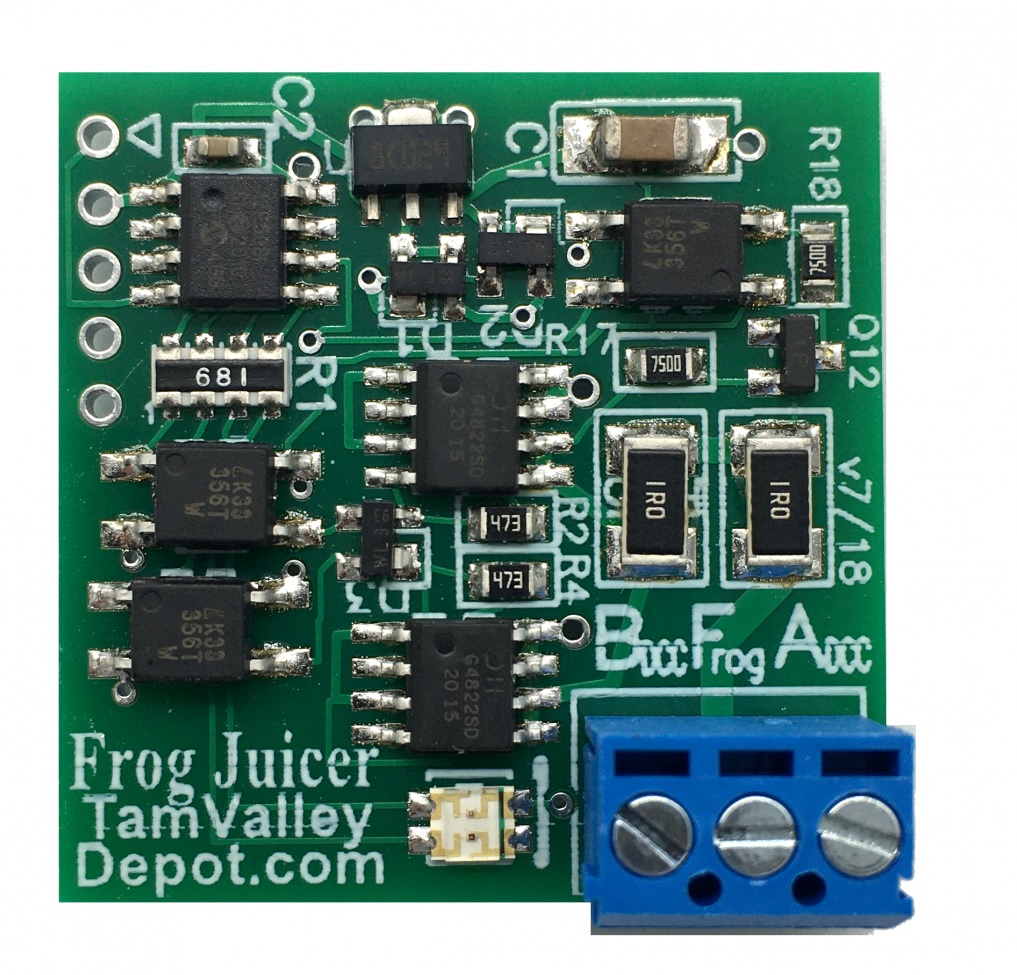
I’ve used both many times and both are very good. Although the Frog Juicer is slightly more expensive it does come with screw connections so soldering is not required.
When it comes to upgrading to DCC there are other ways to try and overcome the problem of shorting, but as a permanent solution with Insulfrogs this fix can be done without lifting the track or replacing it, and enables trains to run smoothly so you can get on with enjoying your layout.

You must be logged in to post a comment.