A Baldwin DT6-6-2000 in HO – Window Shades Part 12

As with all my projects, the further I get into them the more I find out about the real locomotive.  As this model is HO, roughly twice the size of my first N scale version, a lot of the details are more visible, and this means they stand out more if I get them wrong. I’m in the process of drawing up the brass additions and I realized I hadn’t accounted for the sun visors often depicted in the photos of the originals.  But the more I looked into this the more I realized there were lots of varieties.  So in this post, I’ll share some of those with you and explain how I can make it easy to model the right one for you.

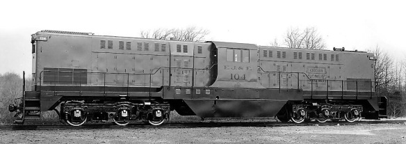
My original model in N Scale was based on Santa Fe’s No. 2601, and so will be the first HO model.  But the first actual Baldwin DT6-6-2000 as originally delivered went to the Elgin, Joliet, and Eastern Railway as a demonstrator and is pictured below.  Several things stand out to me about this loco, compared to the SF 2601.  The grills at each end are at the top of the hoods, there’s no large shaped plate covering the fuel tank, there are no walkways at each end (which apparently was done to shorten the locomotive), the horn is on the side of the hood, there’s a handrail on the side of the hoods either side of the cab, there are round items on the roof which may be fans, and the main cab windows are bare.  It also looks to me like the cab is narrower? (Uncredited image – If you know where this image originates from please drop me a message).

Of course, these things would be easy for me to alter and create a new shell specifically for this locomotive. The chassis and fit would be the same.

The EJ&E had the largest number of DT6-6-2000s and the subsequent locomotives, such as No.104 pictured below, are basically the same as the SF 2601, which is good news.  The main windows have the same triple glass but no sun visors. (Uncredited image – If you know where this image originates from please drop me a message).

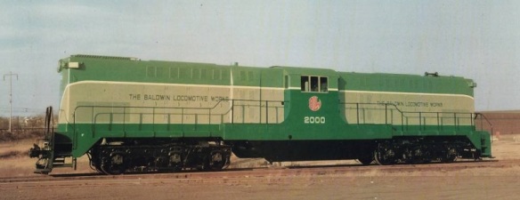
The Baldwin locomotive company made two demonstrators. One of them, No. 2000 (pictured below) was purchased by the SF and became SF No. 2606, again this has no sun visors. ()

The Santa Fe 2602 and 2601, as pictured below (from http://www.snowcrest.net/photobob/sfl2.html), both had sun visors over the main window, no doubt due to the continuous fantastic California sun!  The sun visor appears to be fabric with a frame holding it out over the window, I assume so it can be retracted.

The Trona Railway locomotive No. 51 also had a similar sun visor configuration but I’m not sure if it’s damaged or adjusted to not cover the whole window? (Photo from Vernon Ryder, Jr.- collection of Mark Laundry – http://baldwindiesels.railfan.net/trona/index.html).

Pennsylvania Railroad No 8954, which is actually an RT-624, has what looks like the same thing, just folded up. (Uncredited image – If you know where this image originates from please drop me a message).

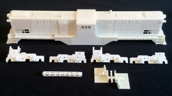
To model this in N Scale I added a simple shape to the etched brass Additions, shown below in the bottom right-hand corner.

These are stuck to the side of the shell with the tiny arms folding back to act as props, and they work well.

But I did find that if the visor received a knock it could easily come off. To overcome this on my Alco C-855 shell, also for N Scale, I 3D printed a sloping slot into the side of the shell.  The visor was again etched brass but didn’t need any folding; the blades simply slid into the slots.

A little glue on each blade is more than enough to hold it firmly in place.  This is much stronger and ensures the visor is in the right place and at the correct angle.

I can do something similar with the HO DT6-6-2000 but should you wish to have a model without them you will have two holes in the side of the model.  But the joy of 3D printing is I can make different versions of the shell available, one with holes and one without.  I’ll do a similar thing for the Pennsylvania Railroad DT6-6-2000s and RT-624s, which have train antennas. The etch brass Additions however are not so simple as an etching tool has to be made, which gets reused but can’t be changed, so I’ll simply make the sun visors and train antennas available on each etched fret.

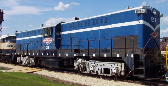
There’s also one more option which I discovered.  The Minneapolis, Northfield, and Southern Railway, as well as later EJ&E locomotives, had a metal-framed glass window extension which, I assume, allowed better visibility for the crew.  MN&SR No. 21 is the last surviving DT6-6-2000 and can be found at the Illinois Railway Museum where it remains in operable condition and affectionally known as ‘The Blue Dragon’.  Below you can see the glass window projecting out from the cab. (Picture from Illinois Railway Museum http://www.railroadmichigan.com/illinoisrailwaymuseum.html).

This third option will be a little tricky to 3D print as it will possibly make it too chunky, spoiling the look, and it’ll be a weak structure.  But it’s possible to make it from etched brass.  If this is the answer then it will again appear on all of the etches.  To ensure a strong fixing the etch will again slot into the shell.  There will need to be two different etches, as the handrails, which are the largest part, are different on the RT-624 from the DT6-6-2000 and to put them all onto one fret will take up way too much space.

So now I just need to figure out how to fit all the parts onto the etching sheet.  Hopefully next week I can share that with you and get it sent off to the etcher.

A Baldwin DT6-6-2000 in HO – Test Print Part 11

In last week’s post, which you can find here, I shared with you the first images of the new HO Scale Baldwin DT6-6-2000.  I’ve now had some time to test it out and this week I’ll share with you some of the results.

As you may remember the new 3D printed shell fits on top of a Bowser chassis taken from an Alco C-630, as shown below.  The chassis is fairly standard and has two mounting holes at each end.  The shell fitted perfectly over the chassis once I’d poked the wires up inside, with the exception of the lugs at each end.  They were about 1/2 mm longer than expected, or rather the shell was 1/2 mm shorter than drawn.  This can happen and is called ‘shrinkage’.  When a 3D print, at least one printed in this material, comes out of the printer it’s heated to make all the support material liquefy and run off, then it’s left to cool.  This is a very precise system and shrinkage can occur if the timing of the heating and cooling is not spot on.  All the prints do it but the difference is normally negligible.  But, given the size of the print, 1/2mm shrinkage over the whole length is very acceptable, and I’ve adjusted the 3D model to allow for this.

The most disappointing thing was the locating hole for the connecting bolt.  If you remember I designed the shell to have a hexagonal hole to receive a nut that could be glued in place, as shown in the image below.  Sadly I didn’t allow enough tolerance; it’s too tight a fit for the nut.  For this particular shell I can file down the nut to make it fit, but for the actual shell that will be for sale I’ve made the hexagonal hole bigger.

The other hole close by is the off-center mount for the tiny motor that will power the Kadee uncoupler.  This was a tight fit but went in exactly as planned, although I’ve now added a little more tolerance.  I think the reason for the tight fit here was 3D print residue inside the hole, but it’s nearly impossible to get into the hole from inside the shell to clean it out so increasing the size was easier.

My cable loops also worked very well; using a pair of tweezers I was able to thread the wires through the loops which will keep them clear of the drive shafts.  I also fitted an LED which will be for the headlight; I used a yellow one just so it shows up in the photo.  The final one will be clear and emit a warm white light.

From the front the LED pokes though the 3D printed hole in the headlight and allows a lens to be placed in front if required.

The coupling didn’t fit perfectly the first time as I managed to get the hole for the Kadee in the wrong place; possibly I originally measured the wrong coupling? However, I was able to trim the coupling so it slid back a little further, and secured it with a screw.  It works well and is the right height.  I haven’t tried it yet with the motor to make it powered.

The cab interiors and horns were easily snipped off their sprew.  The tail on the bottom of the cab interiors allows them to be held with tweezers when fitting inside the shell.

The horns fitted right in, but having them loose allows for different horns to be fitted.  I’ll probably add different horns to the sprew, giving a choice

The cabs fitted perfectly as well; below you can see one cab fitted.  The recess for the cab light is just about visible where the other cab goes.  I haven’t tested these but as they’re so small I have no doubt they will fit.

With both cabs fitted you can see the backs of the cabs form the same width as the channel in the shell, allowing the chassis to fit in.

The crew are now visible through the window.  The N Scale version also has this, but in HO it will be much more visible.

Of course, test fitting is great, and I’m pleased I did it so I could fix the few issues that arose, but the real test is how does it run?  Last week I took the locomotive down to the workshop and ran it on a HO layout we’re currently building for a customer and it ran perfectly.  I managed to get a few quick videos.

For the test I simply fitted a basic DCC decoder without any setup and ran it.  This also has the 3D printed truck centers and gears so the trucks are rotated the right way for a DT6-6-2000.

The next stage now is for the brass to be drawn and etched and to test fit that, but with the 3D print issues resolved and the shrinkage accounted for on this scale, I think you’ll agree that this locomotive is very nearly ready to be made available.

A Baldwin DT6-6-2000 in HO – Test Print Part 10

It’s been two weeks since my last post but I’ve not been idle.  I finished the modeling for the HO Scale Baldwin DT6-6-2000 and sent the file off to be test printed at Shapeways.  And last Friday the 3D model arrived, so this week I’ll share with you some images of how it came out.

The test print was ordered in Shapeways’ Smooth Fine Detail plastic, which is an acrylic.  This is the material with the finest detail and allows for the highest accuracy with parts.  It’s the material I use for just about all my locomotive shells and parts.  3D prints always need to be cleaned when they arrive as they have residue on them from the print process.  I normally do this by soaking the parts in Goo Gone, but this time I used White Spirit.  The White Spirit I use has no other chemical in it that will affect the parts; it’s always worth checking before you use it to soak the 3D printed part.  After a 24-hour soak, followed by a wash off under the tap, all the parts turn white; this takes about half an hour.  I then leave them overnight and any remaining residue will turn into a white powder which can be brushed off. I use a brush in a Dremel tool; this is the same method I used on my O scale tenders which you can read about here.  The big difference between the O scale tenders and these models is the quality of the print.  Now that I can specify the orientation of the print I can ensure they are printed the right way up, which gives a smooth surface on top and down the sides.  If you’re wondering why I don’t use White Spirit to clean all my prints, it’s because of the fumes.  Indoors White Spirit lingers for days, Goo Gone doesn’t, but in this instance I didn’t have enough Goo Gone to hand for the size of the model.

The test print was for the whole kit; shell, truck centers, truck gears, crew and horns.

The truck gears come in a cage to keep the cost down and stop them from getting lost.

The two cab interiors with crew are attached to each other and the horns are attached to the linked piece.  These can easily be cut off.

I have to say I’m very pleased with the print. The top and roof are very smooth and the details are crisp.  Being an N Scale modeler it also seems massive!

I’m also very pleased that it’s so robust.  The N Scale version was designed almost on the minimal limit of material thickness to ensure it fitted over the donor chassis without making it wider than the real locomotive.  For the HO model, I left the thickness the same, meaning when it’s scaled up to HO the material is almost twice as thick making it much stronger.  The shell doesn’t flex when squeezed.  Given the weight of the chassis and the fact that the trainload will be conducted through the coupling, which is attached to the shell not the chassis, having a strong shell was important

Most of the detail was already on my N Scale version but it really pops out in HO.

Inside the shell, you can see the loops I printed into the shell roof for my wire runs.  Getting the wires into them will be tricky but worth it, as it’ll keep everything tidy and clear of the drive shafts and rotating truck towers.

The underside of the pilot is a little rougher, as this was the underside of the print, but you can clearly see the bolt hole for mounting the chassis, Kadee Coupling mount hole, and the off-center hole for the powered coupling motor.

The detail on the nose and pilot was again on the N scale version, but it has come out so well.  The modeled lever for operating the coupling often gets overlooked or broken on the N Scale version, but here it is clear and strong.

All the detail on the top is clear including the lifting eyes, radiators, exhausts, and riveted plates.

The chassis, as you may remember from my previous posts, had already had one of its trucks rotated by using the new 3D printed truck centers and gears.  Now both are done.

The right-hand truck was the first one done, but it hasn’t been cleaned in White Spirit or Goo Gone so it’s still opaque, as are the gears.

The left-hand truck is all white after cleaning but this has no effect on the running.  Note the printed gears and black original gears are positioned differently in each truck but again this has no effect on the running.  The holes for the gear spindles did need to be reamed out with a drill to allow the gears to spin.

The shell is now fixed onto the chassis and ready for a test run.  I only have a foot and a half of HO track at home so it’ll have to wait until I take it to the workshop tomorrow for a proper test, but I’ll get some video.

I still have the other parts to test fit such as the cabs and horns, but I’ll get that done this week.

The next task is to finish drawing the brass parts and get them ready for etching.  Once they come back, and assuming everything fits, the kit will be made available to buy followed by the various different versions of this great locomotive.