New Drive Shafts For Bachmann OO Class 46

This week I have a new product to share with you. As with most of my replacement parts, they’ve been designed and produced because a customer’s model has a broken part that’s no longer available from the manufacturers. And this week’s part is precisely for that reason.

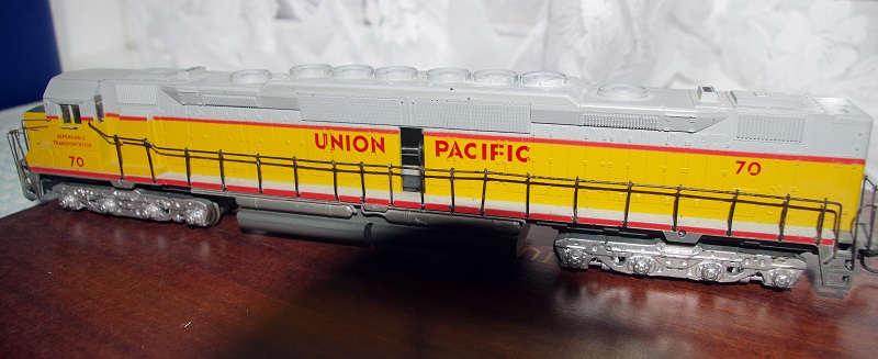
Bachmann’s OO scale class 45 and 46 locomotives that were sold in the blue box and advertised as the new ‘Super Smooth Fly Wheel Gear Drive Motor’ came out in the mid-1990s and are normally very good runners, super smooth as it says on the box. These models have since been superseded by Bachmann so parts are no longer available.

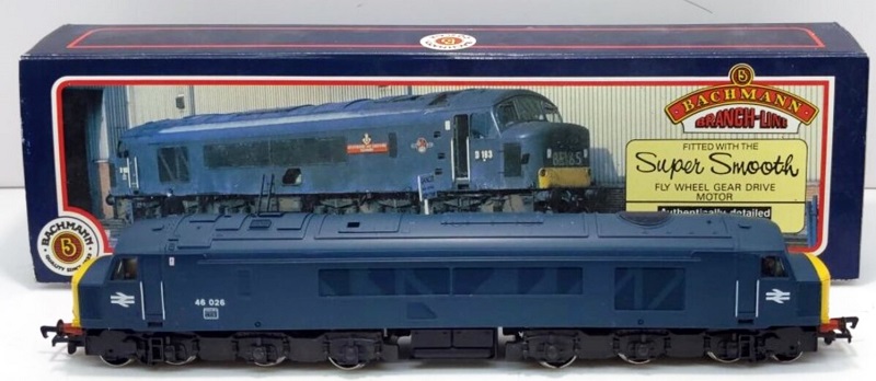
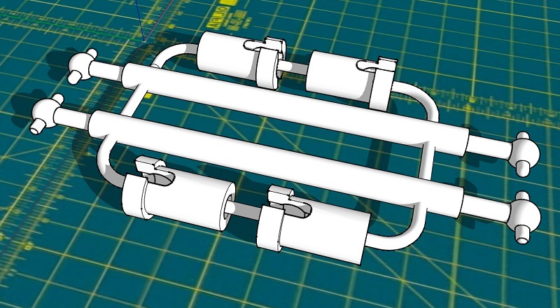
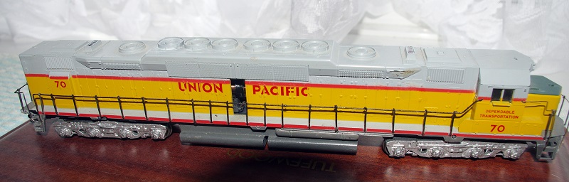
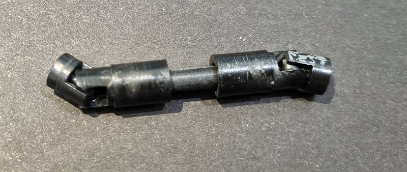
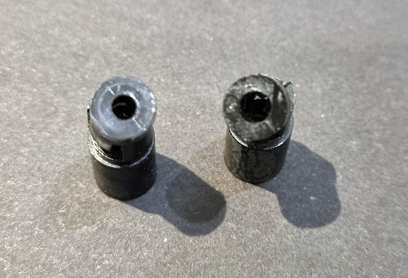
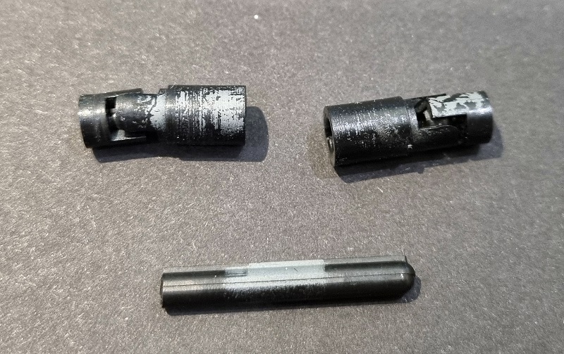
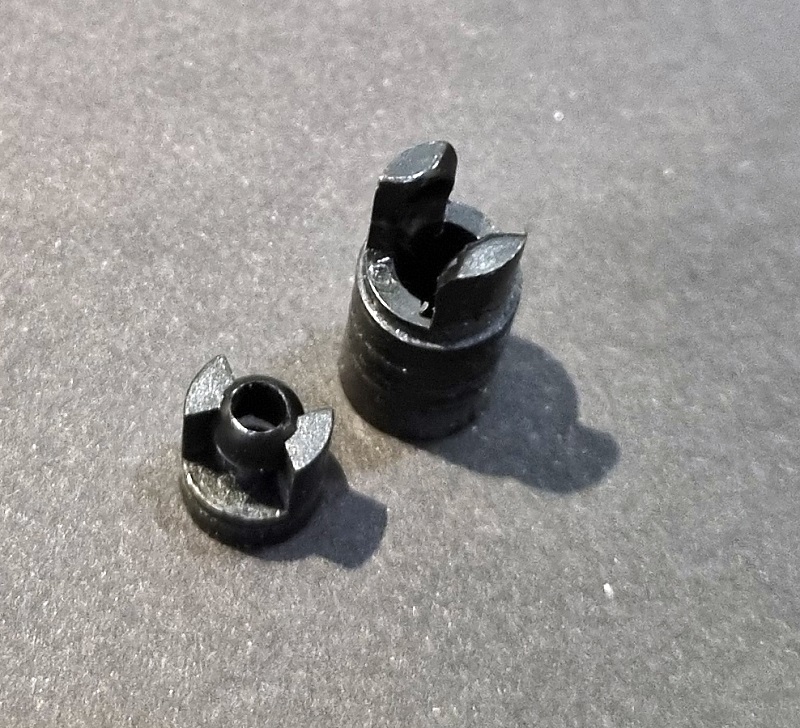
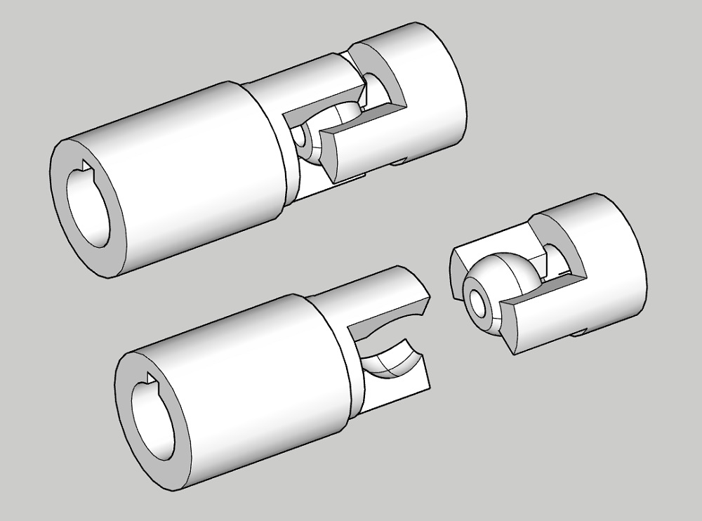
Compared to other manufacturers’ models at the time that often had a single powered bogie at one end, this has a heavy centred motor that powers both bogies via swivelling drive shafts. However, as we’ve seen with several other models such as the Athearn DD35A from a few weeks ago, the plastic parts of these drive shafts can start to break with age. The primary cause of failure is due to the fact that they are press-fitted onto a metal shaft and the continuous outwards force eventually cracks the plastic.

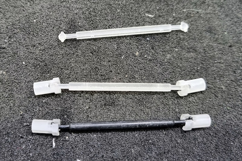
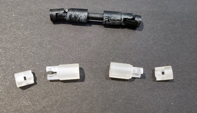
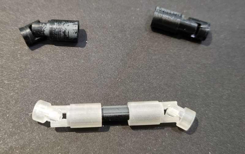
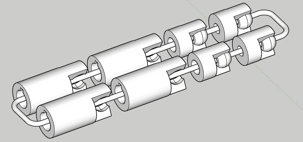
To repair these locomotives I’ve made a kit available containing two complete drive shaft assemblies.

The parts have been printed in Shapeways Smooth Fine Detail material for its hardness and accuracy.

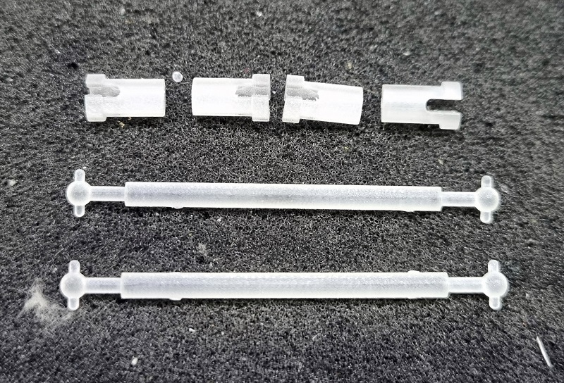
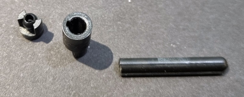
There is a ball joint for each end of the drive shafts which connect to the motor or worm gear spindle.

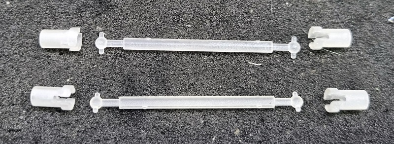
I’ve designed them so they work with the existing parts, therefore you can change just the parts that are damaged or everything.

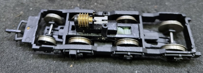
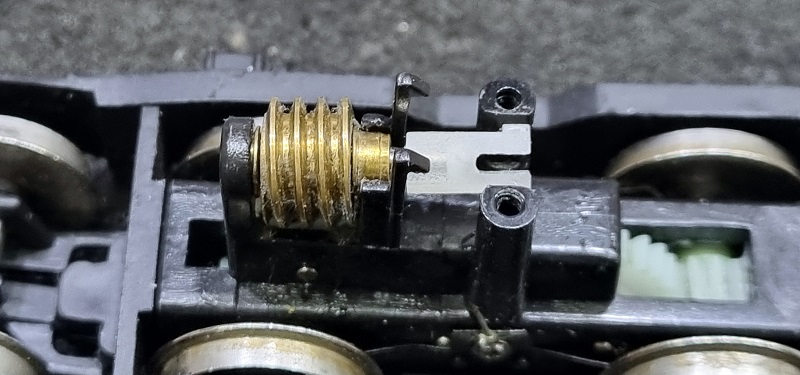
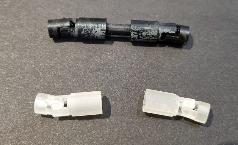
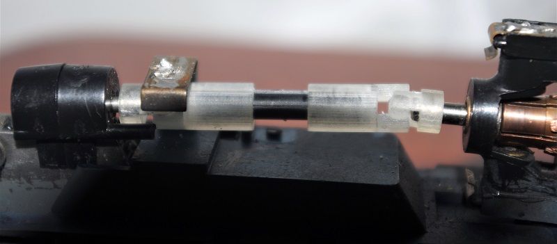
The bogie for this locomotive only has power to the center wheels via the plastic tower gears. The metal worm gear sits in brass bearings on top of the bogie tower.

It’s the ball joint that connects to this spindle that I find breaks in most cases with these locomotives, so I only replaced this part and used the original driveshaft to get this locomotive back on the layout.

If you have a Bachmann Class 45 to 46 with this issue, you can get the drive shaft kit here.

If you’re a regular reader of my blog you may have noticed several gaps in what I had intended to be weekly posts. However, there’s a good reason for this and I’ll be making an exciting announcement in roughly three weeks. Until then it’s back to the drawing board.

A New Drive Shaft For An Athearn DD35A

As well as replacement gear sets I also do a lot of replacement driveshafts and this week I have a 3D print project to share with you that repairs an old Athearn HO DD35A.

These big locomotives have two motors, just like the real thing. Each motor has a drive shaft that connects to the top of the truck and, through a set of gears, drives the wheels. But as the truck swivels the drive shaft has to adjust in direction and length. This is done by the use of universal joints and a sliding driveshaft. The ends of the universal joints are press-fitted onto the metal shafts of the motor and truck. And it’s at this point where they fail; the plastic cracks with age and no longer grips the metal shaft, preventing it from turning. Below is an original complete drive shaft with two universal joints and a sliding centre shaft.

You can just make out the cracks in the plastic in the image below on the right. Oddly the metal shaft on the motor (the universal on the right) is larger than the truck as you can see by the different hole sizes.

The sliding shaft has a keyway along its length; you can see it below on the top of the shaft.

The end of the universal this connects with has a slot for the keyway to fit into. This means the drive shaft will always turn the universal but can slide in and out.

The universal itself consists of a ball and socket configuration and press-fits together.

Using the original parts I was able to 3D model both ends of the universal, also taking into account the different metal shaft sizes. I needed to design the joint so it clips together and won’t easily pull apart, but is not such a tight fit that it cracks on assembly or prevents it from moving freely.

The 3D printed parts were printed in Shapeways Smooth Fine Detail material because it’s very accurate and hard, which is ideal for this use.

The two halves of the universal pushed together with a satisfying click and held in place, but allowed full movement. The ones shown here were the first test print and the tabs that hold the ball were a little weak. One did break so I thickened this up for the second test print.

The original driveshaft also fitted smoothly with its keyway.

The last thing to do was fit the new universals to the locomotive. As with all my gears and parts that press-fit, the holes in the ends needed to be cleaned of 3D print residue before fitting. If this is not done the chance of cracking the new parts is high as they’re a tight fit by design. These were reamed out with a drill bit slightly smaller than the metal shaft. If it’s the same size the part will no longer be a press fit. You might be able to see in this photo that the tabs holding the ball are larger as these are the second test print.

The loco now runs as good as new and is ready to go back to the layout.

A set containing enough parts to replace all four universal kits can be found here.

If you have a part like this on a locomotive that you can’t find a replacement for, please get in touch and we’ll discuss making a new one for you.

New Axles for a Second Generation Bachmann HO 4-8-4 Northern – Part 3

Happy New Year!

For the first post of the New Year, I thought I’d start by releasing a new product that would also finish a project started last year.

The second generation of the Bachmann HO 4-8-4 locomotives, just like the first generation, has an issue with splitting axles so I’ve designed a set of 3D printed replacements. You can read the first post about this here and the second here.

The second generation 4-8-4 chassis is an improvement on the first and has a much thicker drive gear, which in turn means it has stronger teeth. This means the 3D printed gear axle can be a direct copy of the original, although I’ve made some very minor changes to the overall design.

The replacement axle set will contain three axles and one gear. As you can see below the axles all have square holes which makes quartering (setting up the valve gear and side rods) much easier, because each wheel can only fit at 90° rotations. One thing that’s important is to clean out this square hole as it will almost certainly have some 3D print residue inside. Although this is a waxy substance it still has a thickness and if the wheel is inserted before removing this, the fit will be too tight and the replacement axle may crack. I use a very small flat blade screwdriver, or needle file with a square point to run along the square hole corner and scrape out the residue.

If the original gears have split and no attempt has been made to fix this then the old parts can simply be pulled out, they may even fall out, and the new parts can be put in. But if an attempt to repair the original axles with glue has been made then this will need to be cleaned up. On the model below the rear two axles came right out but the front two have been glued. Using a pair of side cutters I cut or rather cracked the axle in half.

Some parts then fell away but some remained stuck, so I used some pliers to pull them out. When doing this be mindful of what you’re holding onto and how the force of pulling is restrained, as you don’t want to bend and mangle the side rods and valve gear.

With all the plastic removed the void in the wheel will probably still have glue in it as you can see below. This will also have to be removed. How you do this will depend on the type of glue used, but the wheel is made from metal with a hard plated surface so normally it can be scraped off. I tend to use a mixture of a small flat screwdriver, craft knife and tweezers. I tend not to use files or anything abrasive that can damage the wheel.

To see if all the glue has been removed one trick I discovered is to use one of the old axles, if you still have one intact that is, to test and see if it fits. It doesn’t matter if the old axle is cracking, as long as you can fit it into the wheel. Below you can see the axle fitted onto a wheel that wasn’t glued. There’s a small gap between the wheel and the step on the axle which is correct.

Fitting the old cracked axle into the wheel with the glue, you can see it won’t go in as far, because there’s still some glue in the base of the wheel void. So this’ll need to be removed.

Once all the glue is removed the wheel void should look something like this. All the metal surfaces I scraped with the tools are now shiny, any glue even if transparent would show up as a dull area.

With all the wheel voids cleaned up and a test fit done with an old axle, the new axles and gear can be fitted.

With the wheels pushed all the way in, this should leave that small gap between the wheel and step on the axle; the wheels should be at the right spacing. But it’s always a good idea to check this with a wheel gauge. For HO and OO gauges 14.4mm (0.5669″) is the correct spacing from the back of each wheel, commonly known as the ‘back-to-back’. If the gauge is too tight a wheel can be pulled out ever-so-slightly. Be careful not to twist the wheel when doing this as you can crack the axle. If the gauge is loose then one of the wheels need to be pushed in further.

And that’s it, the base plate can be refitted and the locomotive is ready to go.

My replacement axle and gear kit for the Bachmann HO 4-8-4 Second Generation is available here.

Next week I intend to share an update for the HO Baldwin RT-624 project with you.

A Dummy Knuckle Coupler for OO Gauge – Part 4

Back in September of 2019 I released my OO gauge dummy knuckle couplings which are designed to fit into NEM pockets on locomotives and wagons; you can read the post here.

These have the advantage of connecting directly to Kadee couplings without the risk of disconnecting. They are also 2mm taller than the normal Kadee couplings to allow for the different manufactures’ NEM pocket heights.

However, the need for a slightly shorter version has been highlighted so I’ve now made that available too.

Using two of my original couplings, the distance between the face of the NEM pockets is 20mm. The shorter version gives 18mm. The two millimeters doesn’t sound a lot, but in a rake of wagons it can make a big difference.

I have renamed the original releases slightly to differentiate them from the new ones. The ‘large’ refers to the knuckle height, not the length.

OO NEM Dummy Knuckle Coupling 9mm (Large) x10

OO NEM Dummy Knuckle Coupling 9mm (Large) x26

OO NEM Dummy Knuckle Coupling 9mm (Large) x50

OO NEM Dummy Knuckle Coupling 9mm (Large) x150

OO NEM Dummy Knuckle Coupling 10mm (Large) x10

OO NEM Dummy Knuckle Coupling 10mm (Large) x26

OO NEM Dummy Knuckle Coupling10mm (Large) x50

OO NEM Dummy Knuckle Coupling 10mm (Large) x150

These are now all available using the links above.

If you require a different length please get in touch and I’ll make it available as well.

New Gears For A Bachmann N Scale Street Car & Brill Trolley

This is a project that I started at the beginning of 2020 so it’s about time I shared it with you. The Bachmann PCC Interurban Streamlined Car has been around since 1983 and was released in a large variety of paint schemes and liveries. However, all the models released up until about 2000, when Bachmann upgraded the chassis, suffer from the same problem; the white plastic gears on the axles crack. In this post I’ll share with you my 3D printed replacements to fix this.

The PCC Interurban Streamlined Car, and similar Brill Trolley released the year before, share a similar chassis with the same trucks. The body is all plastic and clips over the metal chassis, which fills the body.

The underside is fairly basic and you can see all four axles are driven via gears. These are the gears that crack under the pressure of the metal axles press fitted into them.

With the body removed you can see the chassis, which is made of two halves and separated by Bachmann standard fastener and washer system. Should these brake I’ve made replacements available here.

With the two screws removed the chassis haves come apart and the trucks fall out, although the repair can be done without separating the chassis or removing the trucks if you wish.

The large drive gear in the centre of the truck doesn’t have any issues.

The wheels have a short axle which press fits into the gear, when fully inserted the two axles do not touch each other so the gear also forms the electrical isolation. The wheels should just pull out. If the gears are cracked they’ll come out very easily.

The original gears, as shown on the right of the photo below, are made from a material that’s prone to cracking and you can see the light change as it hits the crack in the gear. With the metal wheel inserted the crack opens up. This causes two issues; firstly the spacing between two of the teeth is larger than the rest and causes a bump as the gear turns or jams the other gear. The second issue is there is little friction between the gear and the axles so the gear may turn, but the wheel won’t.

3D printing a set of four to replace all the gears is the answer and given the small size of these gears, roughly 5mm (0.196″) diameter, the best material is Shapeways Smooth Fine Detail because of its accuracy and hard-wearing properties. All four have been printed on a sprue so they don’t get lost in the printer.

Unlike injection moulding the sprue doesn’t actually touch the gears, it just passes through the hole in the middle. This can easily be cut with side cutters and the gears are ready to use, although I would recommend cleaning out the hole in the axles of any 3D print residue before you use them.

Refitting the gears and wheels is fairly simple. Position the new axle gear inside the truck and lightly push the wheel axle through the hole in the truck and into the gear. With both wheels lightly fitted, press the wheels together to press fit them firmly into the gear, just don’t push them in too far. The inside distance between the back of the wheels, commonly known as the Back-To-Back dimension, should be 7.65mm (0.301″).

Even if only one of your gears is cracked I would recommend changing all four as it’s probable the others will crack once you start using it again.

And that’s it, the street car is ready to use. The set of four gear axles can be found here.

I have several new gears for different loco types and scales to share with you over the next few months, but if you have something that needs a gear, get in touch. Just like this project I started last year, I may have all ready done it!

A Baldwin RT-624 in HO – Now Available

This week, as promised, I’ve made the HO Baldwin RT-624 kits available to purchase. They’ve now passed all of my checks and had all the little improvements made.

There are two kits available, and both look very smilier but there are differences. Below is the first version.

This kit is for the early Pennsylvania Railroad RT-624 locomotives with the Trainphone. The kit has three parts; the main 3D printed shell, 3D printed detail parts, and etched brass Additions. The 3D printed detail parts and etched brass are the same for both versions.

The second version is for the later Pennsylvania Railroad RT-624 locomotives without the Trainphone. It also has some body differences such as a different headlight position.

The donor chassis used for this model is a Bowser C-628 or C-630, the kit does not come with this.

Please also note that these locomotives have the correct asymmetric trucks but they’re facing the wrong way round. It will work but in order to make it look right you will need to rotate the trucks. As with my DT-6-6-2000 kit I developed a 3D printed kit for rotating the bowser trucks and re-using their side frames. (Bowser sell the correct side frames as spare parts if your donor chassis has the wrong ones).

All the parts are available from the links below;

Early PRR HO RT-624 Body Shell

Late PRR HO RT-624 Body Shell

3D Printed Detail Parts (For both versions)

Etched Brass Additions (For both versions)

3D Printed Truck Rotation Kit (DT-6-6-2000 Kit also for all RT-624 versions)

Commonwealth truck side frames are available from Bowser with their kit 96-603; it can also be used to upgrade an older Stewart Chassis to better pick up if that’s the one you have.  It can be found at the bottom right of the Bowser page using the link below. (If these become hard to get let me know, I can make a 3D printed set of side frames available.)

https://www.bowser-trains.com/instructions.html

The couplings for this locomotive has been designed as Kadee #148 HO Scale 140-Series Whisker® Metal Couplers with Gearboxes – Universal – Medium (9/32″) Centerset Shank.

https://www.kadee.com/ho-scale-couplers-c-274_276_284/148-ho-scale-140series-whisker-metal-couplers-with-gearboxes-universal-medium-932-centerset-shank-p-298.htm

These locomotives have also been designed to receive powered Kadee couplings using Precimodels motors. To make the couplings powered you’ll need the Precimodels kit.

https://www.precimodels.com/en/

The last shell in the HO RT-624 range will be the single Minneapolis Northfield & Southern locomotive numbered Twenty-Five which I’ll soon have finished.

If you have any issue ordering or any questions please let me know. Ready-To-Run versions can be made on request if you prefer, please contact me via the contact page for a quote.

Now the kits are finished I’m going to paint up the two test prints. I have an ATSF DT6-6-2000 and an early PRR RT-624 which I think will look great, and I’ll share them with you once done.