A New Drive Shaft For a MDC/Roundhouse/Athearn 2-8-0

A few months ago at the 2014 NMRA(BR) winter meet in Benson, England, I had an unfortunate breakdown with one of my small steam engines.  Upon putting the engine on the track and turning up the power the engine stubbornly stood still even though the motor was spinning frantically.  After inspecting the engine it was obvious that the drive shaft was missing.  So in this post I wanted to share with you how I have fixed it.

The engine in question is an N Scale 2-8-0 steam engine made by Roundhouse (formally Model Die Casting). Sierra 2-8-0 No 28

These are great models and run like sewing machines.  Due to the size there is next to no room inside for big motors and drive parts so Roundhouse installed a small motor in the tender, they even managed to fit in a small brass fly wheel.  The motor connects to the locomotive via a drive shaft which protrudes from the tender into the back of the cab.  The drive shaft then turns a worm gear in the boiler which connects to gears on the axles, consequently driving the wheels.  Because the tender is hinged where it joins onto the back of the engine the drive shaft has to be flexible.  This has been done using a form of ball joint. The balls on the ends of the drive shaft press fit into sockets and are held in place by the springiness of the plastic sockets.  Normally this configuration would simply spin in the sockets but the balls on the end of the drive shaft has two spigots sticking out from each ball.  Each socket has slots corresponding to the spigots so when the drive shaft turns so does the socket while allowing for the movement of the tender.

The drive shaft is made form black plastic and is very small, measuring only 11.25mm long with a diameter of 0.7mm.  So not to be beaten I decided to 3D print a new one.  Luckily I have a another Roundhouse 2-8-0 so I was able to pop out the drive shaft, pictured below, and copy the dimensions. MDC Old Drive Shaft

This was s fairly simple model, the main concern was getting the length and diameters correct.

Roundhouse 2-8-0 Drive Shaft

Then it was off to the printer and a week later I now have a replacement drive shaft.  I printed this in FUD but it should be printable in WS&F or BS&F as well.

After an overnight soak in Goo Gone and a wash off it was ready for a coat of paint.  Pictured below, the drive shaft on the left is the original, the one on the right has been painted.MDC Drive Shafts - New & Old

I first test fitted an unpainted drive shaft, which was successful, then once the paint was dry I fitted the black painted one.  Make sure the pegs in the drive shaft line up with the slots in the socket before you push it in.  It takes a reasonable amount of force to push the ball into the socket and if the pegs are not lined up they will snap off.MDC 2-8-0 No Drive Shaft MDC 2-8-0 White Drive Shaft

MDC 2-8-0 Black Drive Shaft

And there you go, a repaired Roundhouse 2-8-0 with a 3D printed drive shaft.

If you too have been unlucky enough to loose your drive shaft from either a 2-6-0 or 2-8-0 by MRC/Roundhouse or even the newer Athearn ones you can get a replacement here.  I also do a set of two, just in-case you need a spare which you can get here.


*News* – Shapeways Normal Service Has Resumed

The issue with the Shapeways site has been resolved and the models are back up in my shop. Shapeways have rectified the problem with their search facility which was causing the problem and you should be able to shop now without any further issues, but please email me at jamestrainparts@yahoo.co.uk if you are still experiencing difficulties. Thank you for your patience.

*News* – Shapeways Experiencing Technical Difficulties

I know it is not my usual posting night but I wanted to let you all know that Shapeways are currently experiencing some technical difficulties with their website.  Not all of my models are currently visible and some models are not able to be ordered at present.  Shapeways are doing all they can to resolve this issue as soon as possible. Apologies for the inconvenience, and I’ll post again as soon as the issue has been resolved.

A Baldwin DT6-6-2000 Center Cab In N Scale

Over the last few weeks I have been drawing and designing a kit to make an N scale DT6-6-2000 using an Atlas C-628 or C-630 powered chassis. The test print has now been made and in this post I will share with you the results, the small changes I have made and where you can buy your own.

You can read more about the design in Part 1, Part 2 and Part 3 of the drawing process.

Straight out of the Shapeways box the DT6-6-2000 shell looked great.  Even though it was covered in the normal waxy residue I could already see most of the detail, and nothing seemed to be damaged, badly printed or missing.  To get the model ready for initial photos I simply washed the parts in warm soapy water. This still leaves a waxy residue on the parts and they can’t be painted yet, but as you can see from the pictures below it is enough to show you what  it looks like.

DT6-6-2000 Test Print 1

Even though the parts haven’t been properly cleaned yet I couldn’t resist trying them out! First I looked at the truck side frames, and they fitted perfectly.  All the little clips and catches on the Atlas power truck lined up with the printed side frame and it fitted together with a positive click. Below is a comparison showing the Atlas truck side frame on the left and the printed one clipped onto the power truck on the right.

DT6-6-2000 Test Print 9

From the under side you can see the clips and catches as well as the gear holes.

DT6-6-2000 Test Print 10

Having gone this far I had to try them both in the chassis and do a test run.

DT6-6-2000 Test Print 11

The chassis ran perfectly proving the side frames where not too tight on the axle ends and there wasn’t a clearance issue between the underside of the printed side frames and the rail tops etc.

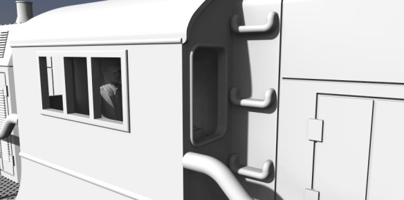
The detail on the actual shell is very crisp as you can see from the photos below showing the exhaust stack, lifting lugs and horns.

DT6-6-2000 Test Print 8 DT6-6-2000 Test Print 4

Even the uncoupling bar that runs across the top of the knuckle coupler has printed perfectly although it is very hard to see in the image below.  When the FUD material is freshly printed and transparent like this it is very difficult to photograph and being wet with waxy residue doesn’t help!

DT6-6-2000 Test Print 7

Next I wanted to test fit the shell on to the chassis but to do that I needed to remove the handrails from inside the shell. As with my EMD DD35 kit I have printed the handrails fixed to the inside of the shell. This is firstly to protect them and secondly to avoid adding expensive material to the model in the form of a sprue.  The handrails are mounted on cross braces that also hold the shell square as you can see below.  Sometimes when a print run is finished the parts cool a little bit too quickly and thus can cause a little bit of distortion, so the braces help prevent that.  If you get a printed model which has distorted you can read about how to fix it here.

DT6-6-2000 Test Print 17

I cut the handrails out using an X-Acto knife but I’d made the ends of the cross braces a little too big which made them hard to cut. I ended up pushing very hard which is not recommended with FUD as it can be a brittle. I have since reduced the ends of the cross braces which will make the hand rails much easier to cut out.  All six hand rails come out in one piece as you can see below.

DT6-6-2000 Test Print 6

The shell was now ready to fit onto the chassis and it slid over the metal frame and located onto the metal lugs with ease.  As one end of the chassis is higher than the other I added locating brackets inside the shell to sit on top of the chassis at the relevant heights; this means the shell will only fit on one way.  In the photo below you can see the lower end is on the left.

DT6-6-2000 Test Print 12

With the shell test fitted the first thing I noticed was the trucks seemed very close to the triangular section next to the front steps.  I was worried that this would prevent the trucks from turning but after doing several tests around a tight corner on my layout I discovered it was not close enough to touch but as a good measure I have moved the triangle away from the truck a little bit more.  The locomotive trundled around my small yard quite happily as you can see below.

DT6-6-2000 Test Print 13

The last big check I wanted to make was the coupling pockets.  The shell has been designed to receive Micro-Trains N scale body mount couplings in a pocket on the underside.  There is a pilot hole ready for the mounting screw and a gap in the pilot to allow the coupling to poke through.  As the pilot hole was full of wax residue, and slightly smaller than the screw diameter by design I drilled out the hole using a #62 tap drill from Micro-trains and taped it using the 00-90 tap from the same tool set.  Once I had assembled the Micro-trains body mount coupler I pushed the screw through the coupler.  The standard screw that comes with the body mount couplers is two long for the shell, it would protrude up through the walkway if left as it is, so I cut it short with a pair of side snips. Please use safety goggles if you are going to do this as the ends fly all over the place.  I left about 2mm (0.078″) of the screw protruding from the coupling and inserted it into the pocket. The screw lined up perfectly with the hole and I was able to do them up.  As FUD is a plastic, don’t over tighten the screw or it will pull out and ruin the thread in the shell. Also if it’s too tight it will prevent the coupler from working properly.  Once both were installed I was able to check their heights and see if they functioned correctly.  I did this using a Micro-Trains N scale coupler height gauge as pictured below.

DT6-6-2000 Test Print 15

The high was perfect.

DT6-6-2000 Test Print 16

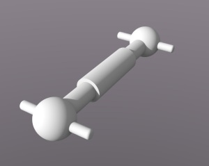
And finally, as you may recall, I also included an engineer for the cab. and here he is.

DT6-6-2000 Test Print 2

He is very small, and this photo doesn’t do him justice.  The only issue I had was not with him but with my design.  I found that even though I had put locating locating lugs in the shell to fix him in the right place it would be very difficut to do as there is nothing to get hold of him by.  So I have now added a tab on the underside so you can grab him with a pair of tweezers.

Now all the checks and tests are complete I’m happy to make the kit available to buy in several options such as unpowered dummies and with or without truck side frames.  You can find them all on the new website page here.

In a future post I will share how my DT6-6-2000 looks painted up in Santa Fe colors transferring freight from one yard to another.


Drawing A Baldwin DT6-6-2000 Center Cab Part 3

So now the DT6-6-2000 is all drawn and the test print has been order it was time to think about the dummy version of the locomotive and how I was going to do it.  In this post I will share with you what I have decided to do.

Below is a rendering of the finished shell sat on the Atlas chassis along with the replacement truck side frames.

Finished Baldwin DT6-6-2000

The dummy version of this locomotive needs to look exactly the same as the powered version as I intend to run them together, recreating Mark McDowell’s image in the link below.

http://www.rrpicturearchives.net/showPicture.aspx?id=219383

The first part to do was the trucks.  Having already created the side frames with all their details and parts for the powered DT6-6-2000, I was able to use the same details for the outer face of the dummy trucks. The inside face of the frames are relatively smooth as they don’t require details, just axle pockets for the wheel sets.  I added the side frames to a similar arrangement I had already used with my UP Water Tenders.  Being a typical draughtsman I don’t draw anything twice if I can hep it.  The trucks for the tenders have evenly spaced wheels so I offset the bolster pin, I did this so the center wheel didn’t need to be removed to install in the pin.  For the DT6-6-2000 I wanted to do the same thing but as the wheels are already unevenly spaced in the trucks this meant the pin could be moved closed to the center of the truck as shown Below.

Baldwin DT6-6-2000 Dummy Truck

The truck has been designed to take 3 Fox Vally 36″ metal wheel sets (FVM3611), there are no couplings because they will be body mounted on the shell.

The truck for the other end is exactly the same, just rotated by 180 degrees.  As with my other trucks these are only printable in the Frosted Ultra Detail material from Shapeways.  This is because of the level of detail and the thin sections that are only achievable in this material, the bolster pins are also printed in the FUD to complete the set.

For the chassis I decided to make it out of the White Strong & Flexible material as I did with my DDA40X dummy chassis.  Because the DT6-6-2000 has those large side plates that hang down over the fuel tanks and air cylinders there is very little, if any, of the chassis that will be seen once the dummy locomotive is assembled.  WS&F is ideal because it is lot cheaper than FUD, it can be printed in black and it doesn’t need to be soaked in a solution to remove the waxy residue left on the FUD parts.

Although it is not really visible I still like to add what detail I can to parts so I included the fuel tanks and air cylinders to the underside of the chassis.  As you can see from the image below the fuel tank is hollow which allows extra weight to be added.  This will be important as the majority of the locomotive will be 3D printed and it will be very light.  With out the extra weight the locomotive will have a tendency to ride up over the rails and come off the tracks, especially if between the powered locomotive and a heavy train whilst going around a tight curve.

Baldwin DT6-6-2000 Dummy Chassis

The chassis looks a lot chunkier than the dummy chassis I produced for my DD35 dummy.  This is because the design requirement for WS&F are thicker than FUD, and it also shorter.  I added the lip around the top of the chassis as a structural element, as with the tie across the top of the up stands.  The bumps on the up stands match the dimples in the shell, but rather than move them down for the dummy I left them in the same location, that way the same shell will fit on either the Atlas chassis or my dummy chassis.  Pictured below are the finished trucks and chassis, they will fit inside the shell using the same fixings and lugs as the Atlas chassis uses. Baldwin DT6-6-2000 Chassis & Trucks

And together the dummy and powered DT6-6-2000s should look something like this.

Baldwin DT6-6-2000 x2

The dummy is in the front, without the fuel and air tank detail on the dummy chassis there would be a big void under the locomotive from this angle.

The test print for the shell is due to arrive this week so in next post I should have an actual model of the DT6-6-2000 to share with you.

Drawing A Baldwin DT6-6-2000 Center Cab Part 2

Over the last few weeks I have been working on the 3D model for the Baldwin DT6-6-2000 center cab locomotive and it is now ready for a test print.  In this post I wanted to share with you some of the details I have included in this new model.

If you missed the first part of this model design you can find it here.  I finished the first part with the image below which showed an overall view of the shell at the then current stage.

Baldwin DT6-6-2000

Since then I have finished all the little details and fixed several of the issues that were not working.  The biggest issue was the size, or to be more precise, the length.  Although the 3D model has been accurately drawn, this shell has been designed to fit onto a powered chassis taken from an Atlas C-628 with the trucks rotated, as I illustrated in the first post.  The issue arose when the trucks were rotated they were not located in the same position as the DT6-6-2000’s trucks and they clashed with the bulkheads at either end.  To resolve this I have added 100mm at each end, which doesn’t sound a lot and in fact, in N scale, it works out to be an extra 1.25mm overall, but having tried to keep it as accurate as possible, suddenly adding 100mm made it look odd.  To hide this I dispersed the 100mm throughout the model by moving door sets up by 10mm etc and I don’t think you’ll be able to tell.  I also had to add about 60mm to the height because of the chassis being slightly taller but once again I don’t think it will be noticeable in N scale.

To make sure this would fit the power chassis snugly I also modeled it in along with all of its lumps, bumps and fixing points so these could be replicated in my 3D printed shell.  Below is an image showing the chassis fitted into the 3D model with half the shell removed.

Baldwin DT6-6-2000 Cut Away

I also modeled in the power chassis trucks without their side frames.  This is because I need to provide new side frames as the C-628 frames are not right for this model.  A fellow modeler has also produced side frames for this locomotive in cast resin and when this kit goes up for sale I will include a link to his website for anybody who would prefer to use those.

My truck side frames for this kit, pictured below, are designed to fit directly onto the power chassis trucks using the same fixing lugs.  The side frames also clamp the power pickup strips to the wheel tips so getting the size of the side frames right is very important; if they are loose the locomotive will have bad power pickup or even worse, will simply fall apart. If they are too tight the wheels may not turn easily and this will overstress the motor.

Baldwin DT6-6-2000 Truck 1

Another issue I ran into was that the C-628 trucks are not only taller but also have a lot more going on.  Consequently, when I put my frames over the power chassis trucks you can see way too much.  To resolve this I had to increase the height of the frames by 60mm and blank off some of the clear spaces. However, as pictured below, I don’t think they look too overworked, and on the plus side it adds strength to the print.

Baldwin DT6-6-2000 Truck 2

The other major detail I have added is the cab interior and engineer.  Just about all of the ready to run locomotives I have ever purchased don’t have engineers or crew in the cabs and given the capabilities of 3D printing it seems silly to leave them out.  The real DT6-6-2000 has a cab which stretches across the whole locomotive, and as there is an engine in each nose section, you can see through to the other side.  However with this model when you look into the cab from the side all you will be able to see is the C-628 metal chassis, so I have designed a cab section with a blanking wall that is a separate part.  As well as hiding the metal chassis this allows you to paint the inside of the cab and the engineer before fixing it into the shell.  I have provided a cab section with an engineer for both sides allowing either one of the engineers to be removed as required.

Baldwin DT6-6-2000 Engineer

The cab and controls look a little basic but remember this is for an N scale locomotive and they will only be visible through the windows, a bit like the image below.

Baldwin DT6-6-2000 Cab

And if the cab was illuminated with a nice yellow light from above this would look great!

The windows have a recess on the inside of the cab to make it easy to fit a small rectangle of clear plastic as glazing; I will provide a template in the instructions for cutting these to the right size. I have also included details such as the air horns, body lifting brackets and steps on the shell as shown below.

DT6-6-2000 Roof Detail

Behind the headlights I have included a cutaway so after drilling through the headlight an LED can easily be pushed in from behind.

The handrails are all separate parts and I have added holes in the shell which match up to lugs in the handrails, which makes them easier to install.  If you want to make your own handrails out of a thinner material, such as brass wire, the holes are designed to be in the right places so they can be used as guides.

And here is the finished 3D model

Finished Baldwin DT6-6-2000

The test print has now been ordered and in a later post I will show you how it came out.