Following on from last week’s post, this week is also about 3D printed replacement gears. Although this week it’s for an N Scale Bachmann 4-8-4 Northern.
The Bachmann 4-8-4 Northern has been around since 1972 and there have been several versions over the years. The first two, with the second released in 1975, are in my opinion rather lumpy runners but it’s the third version, released in 1982, that I’m working on and it wasn’t too bad. However this release suffers from the same problem as the locos in my last two posts; split gears. The loco in the image below is one of these (image from Spookshow.net) and you can see the rear driver is at a different rotation to the rest.

It’s possible that the wheel on the other side of the locomotive is in the correct position but it’s more than probable that it too is misaligned.
The chassis, as shown below, is in one piece with the motor above. The gears sit off-center within the chassis. Each axle is powered by gears so the side rods are cosmetic but if they get out of quarter, as with the loco above, everything jams up. The most common axles to split are the rear two as these are the first to be driven by the motor and therefore under the most stress but it’s not uncommon for all of them to split.

The original axles are asymmetric, that is to say the gear is not in the center of the axle. You can see below the splits on the axles. This releases the friction grip on the wheels, which are simply pressed into the axles, and allows them to spin in the axles.

To start with I 3D printed a set of axles in Shapeways Fine Detail Plastic, formally known as FUD.

Compared to the original they are the same, but the inside diameter of the axle was too big, so there was no grip on the wheels at all.

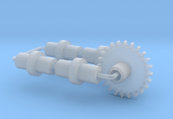
So I 3D printed another set with a smaller inside diameter. I also 3D printed the other gears as it makes sense to supply a full set of replacement gears. This includes the two idler gears and the twin transfer gear that fits under the motor worm.

All the original gears look like this.

Below are the new gears compared with the old.

Test fitting the second set of gears on the axles I found they did fit with a push and I thought that the friction would be enough to prevent them from spinning on the wheels.

To fit the axles properly the chassis plate needs to be fitted between the axles and the wheels. The chassis plate positions the wheels and transfers electric from the metal wheel to the motor; there’s one on each side.

This is the tricky part. When the chassis plate, axles and wheels are fitted to the chassis the wheels must all be at the same position. The position of the axle on the wheel can also affect this as the teeth on the gear need to mesh with the idler gear teeth; if it’s off it will force the wheel to rotate slightly as the teeth mesh. I reckon they had a jig for doing this in the factory.

The wheel sets on the other side must also be fixed so all four are at the same rotation but quartered compared to the other side. To find out what quartering means and why it’s done see the post from two week’s ago here.

On test running, the motor drove all the gears and everything rotated etc but it was lumpy. On inspection one of the wheels was not as well aligned as it should have been and as I attempted to rotated it the wheel spun in the axle. The new axle has not split but it means the diameter of the hole in the axles is still too big and needs to be smaller giving a tighter grip on the wheels. I was reluctant to draw the hole too small to start with because if it’s too small and the wheel is forced in it will probably split the new axle.
Next I’ll make the necessary adjustments to reduce the size of the hole in the computer model and test print another set. Although it fitted okay I’m also going to make a small adjustment to the twin transfer gear as it was also a little too loose. When they arrive I’ll share the outcome with you.


You must be logged in to post a comment.