N Scale Fixed Coupling Drawbar Update

This week I have another product update to share with you.  Unlike last week’s update, for the Minitrix eccentric rod crankpin, which was driven by improving the part, this time it’s simply about reducing the cost to you.

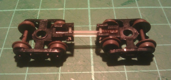
For many years I’ve offered N scale and N Gauge fixed link couplings or drawbars to use between rolling stock or, as I like to use them, between multiple diesels that stay coupled together.  This is really useful if you install a DCC decoder in one locomotive which drives both motors, you can read more about that here.  These drawbars are designed to fit into the Rapido style coupling pockets as you can see below.

To start with these couplings were offered in Shapeways FD (Frosted Detail) material but as that was removed from the available materials they automatically became available in FUD (Frosted Ultra Detail) and sadly the cost went up a bit.  When Shapeways restructured their material pricing again back in June of 2017 these became rather expensive.  However, just as with the Minitrix crank pins from last week I’ve combined the fixed links or drawbars into one piece making them much cheaper to order, as you can see below.

And I’ve also made the primary material BNVP (Black Natural Versatile Plastic) formally known as Black Strong & Flexible.  This is one of the cheaper materials; it’s already a good color for a coupling and can be used right out of the box.  Below you can see a set I’ve already ordered.

These are available in a variety of lengths and all come in packs of 6:

4mm
5mm
6mm
6.5mm
7mm
8mm
9mm
10mm
11mm
12mm
13mm

And if you’re not sure which lengths you need I do have two sample packs available:

Basic Sample Set – Containing 4mm, 5mm, 6mm, 6.5mm, 7mm, 8mm & 9mm.

Full Sample Set – Containing 4mm, 5mm, 6mm, 6.5mm, 7mm, 8mm, 9mm, 10mm, 11mm, 12mm & 13mm.

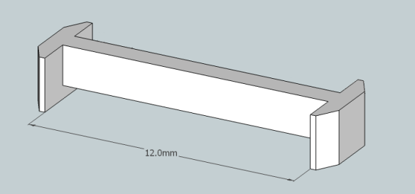
The length refers to the distance from the inside of the coupling pocket, for instance the 12mm is measured like this:

Next week I’ll have some real steam to share with you as I spent a day at ‘The Great Dorset Steam Fair 2018’.

N Scale Minitrx Eccentric Rod Crank Pin Replacement Update

This week I have an update to share with you regarding my N Scale Minitrix eccentric rod crank pin replacements.

Back in September of 2015 I wrote a post about repairing Minitrix steam engines which had suffered with broken eccentric crank pins.  You can find the post here.  These fit A3, A4, 7P (Britannia), 9F, US K4 and US 2-10-0 Decopod steam locomotives.

The crank pin, as illustrated below, has a square peg which fits into the actual wheel and a hole which receives a steel rivet linking it to the eccentric rod.

Although these worked and allowed the repair of the locomotive they did have a few issues.  Their small size made them rather delicate and it was easy to break one when attempting to refit the rivet.  So I originally offered spares in each pack as it was almost certain to happen on your first attempt.

This lead me to improve them by slightly increasing the size of the loop and the size of the rivet hole as shown below, the newer Mk2 pin is at the back.

This did help and made it much easier to reinstall the rivet.  But the issue of re-flaring the rivet was still a problem and I was finding it hard to do as I couldn’t get a supply of new rivets.  This lead me to start cutting part of the loop away to leave a ‘C’ shape which could be forced over the rivet.  As it is a ‘C’ shape it would not fall back off the rivet and the rivet didn’t need to be un-flared in the first place.  The original peg, what was left of it, could be cut away and the new one could simply be clipped in.

But it was hard to cut the hoop in just the right place without braking the hoop.  This lead me to upgrade the model again to include three Mk2 parts with a complete hoop and three Mk3 parts with a ‘C’.  Below you can see the Mk2 and Mk3 crank pins.  Supplying both, I thought, would give you the option as I was unsure as to how well the Mk3 ‘C’ type would work .

Then in June 2017 when Shapeways restructured their pricing system this model became rather expensive as each individual part had an additional $1 handling charge added to the cost.  But the answer is my new Mk4 version of the crank pin which you can see below.

The crank pins are now supplied in a frame.  Although they are not attached to the frame they are 3D printed in the configuration shown above and the loops prevent the cranks from falling out.  The whole model is therefore treated as one piece.

There are eight cranks in each model, allowing for spares, and all have the ‘C’ shaped end which I’ve now used successfully on every loco I’ve repaired since printing the first ‘C’ shaped crank.  Also having spoken to several of my customers they confirmed they didn’t use the cranks with the full hoop at all.

And as the cranks are now held together it makes them easier to not lose!  When you need one simply cut the restraining hoop.

The new Mk4 crank pins can be found here.

Next week I’ll have an update on some of my 3D printed couplings.

Alco C-855 R-T-R Build – Part 3.5 – Chassis Prep Extra

This week I have an extra post to slip into my step-by-step build of an N Scale A-B-A Ready-To-Run set of Alco C-855 locomotives.  Back in July I posted part 3 which covered the chassis preparation procedure, you can find it here.  However I missed something so in this post I’ll cover what it was and how to do it.  My apologies to anybody who has been following this build along with me.  I will update part 3 which will make this post redundant but for now here it is.

You may have noticed I regularly recommend test fitting things as you go and I should take my own advice.  The chassis below has been prepped to fit into a C-855 A unit and at the cab end you can see how the top chassis section has been notched to fit into the narrow nose.

But the lower section doesn’t fit all the way in and a test fit before I assembled the chassis would have told me that.  In the picture below I’ve removed the lower chassis section and placed it into the shell.  As you can see the inside corners of the nose clip the shell.

However this is easily fixed by cutting two notches in the chassis section as marked below.  Each notch is 3.5mm (0.1377“) wide by 2mm (0.0787“) deep leaving a nose of about 6mm (0.2362″) wide.

I cut these out using my Dremel tool and cutting disc.

The bottom chassis section now fits into the shell.

This extra notching is not required for the C-855B chassis as it doesn’t have a nose.  Next, as I have disassembled and resembled the chassis, I’ll test them for running smoothness and any binding in the drive shafts. Then it’s on to the shells which will be in a later post.

Alco C-855 R-T-R Build – Part 5 – Fitting DCC Decoders

This week’s post will be a continuation of my step-by-step build of an N Scale A-B-A ready-to-run set of Alco C-855 locomotives.  And this post will be concentrating on fitting DCC decoders to the modified chassis.  You can find part one of the build here.

Although this post is aimed at DCC installation the first part is also relevant to DC operators.

The chassis, as you can see below, is held together by vertical bolts which clamp the top and bottom sections together.  But the bolts also do more than that.  Instead of a nut on the bottom the bolts screw into the plates which hold in the trucks, and in turn convey the power into the chassis.  The bolts nearest the front of the picture and on the left hand side of the locomotive connect the left power pickup to the top chassis section.  The bolts furthest away and on the right hand side are isolated in plastic sleeves and connect the right power pick up to the lower chassis section.

When these models were new they had a grain-of-wheat bulb connected to the front bolts which was used for the headlight, and illuminated the cab!  But we can now use these as power connections for the DCC decoder.  The original bulb had a diode attached so it wouldn’t operate in reverse.  Con Cor soldered the bulb wire to a tab plate under the bolt head and twisted the stiff diode wire under the other.  As I want to ensure good contact between the chassis and decoder I’ve made another solder tab for the other bolt as can see below.   I made it from an old axle wiper taken from a scrapped locomotive.  The decoder, also shown below, is an N scale sized chip from Gaugemaster but any DCC decoder will work as long as it fits.

Now, before we start with the decoder some electrical bridges need to be added.  This is the part which also needs to be done for DC operation.  In the picture below you can see I’ve linked the two right hand side bots together as well as the left.  This is because where the chassis has been cut and extended the new glued joints can form an isolating barrier.  So if the decoder was simply connected to the two front bolts it wouldn’t receive any power from the rear truck.

The center sections will also be isolated and as the motor used to collect power by having the contact simply touching the chassis, it’ll no longer work.  So the motor wires I’m about to install for DCC will also need to be connected for DC but just back to the solder tabs.

For the DCC decoder the red and black wires are cut short and soldered directly to the solder tabs. They should now be linked to both sets of trucks.

The chip can then be folded in and secured with Kapton tape.  Kapton tape is ideal as it’s isolating, thin, strong and designed to withstand heat in electrical situations.

The gray wire is the bottom motor feed and runs outside the chassis and is soldered onto the bottom motor tab.

There is a wire channel printed into the chassis extension for this wire as you can see below.  This wire, once fitted can be covered in a piece of Kapton tape or glued in.

The orange wire runs halfway down the other side and connects to the top motor tab. It could go through the hole in the top but I like to do it this way.  The blue and white wire are for the headlight so stay at the front.  If you wanted to add a rear light the yellow and another blue would need to be run to the back but as these will run in an A-B-A consist the rear light is not necessary.  With all the wires connected, except for the head light wires which I’m going to cover in a later post, they can now be fixed down.

Again I used Kapton tape to hold the wires down.  It’s important to position the wires in the middle of the chassis as they run from one end to the other as the shell has feet which sit on top of the chassis.  But there’s a gap in the middle of the foot to allow the wires to pass.  The two strips of Kapton tape are where the feet sit.

The chassis is now ready for DCC testing.

The next step is to fit the shell and for that I have to finish painting it which I’ll cover in a later post.