Replacment Short Rapido Couplings

Having spent the majority of my N scale modeling time in the American arena I have not kept up-to-date with the British N gauge modeling scene. However I’ve recently become involved with the Poole and District Model Railway Society in England who focus on British N gauge modeling and I now have the opportunity to find out what’s been going on.

The Rapido coupling has been an industry standard for more than 30 years in both N scale and N gauge and in this post I wanted to share with you some of the things that can be done to make your older British rolling stock with Rapido couplers look comparable to the new NEM coupled stock.

The majority of American N scale modelers and manufacturers have moved away from the Rapido coupling in favour of knuckle couplings from companies like Micro-Trains, formally Kadee.   British N gauge modelers and manufacturers are now also moving away from the Rapido and using NEM couplers from companies like Dapol and Graham Farish.

The classic Repido pictured below is a very simple but extremely functional coupler.  It allows trains to navigate very tight corners whilst remaining strong and reliable.

Rapido Couplings

Because Arnold-Rapido, the inventors, allowed the design to be freely copied by other manufacturers it soon became the standard for the scale.  As shown above there are many variants to the design but the fundamental parts are all the same. Up until recently Rapido was the industry standard but now technology has moved on and manufacturers have started to introduce new coupling designs which look like the real thing in size and shape.  Initially the new design of couplers still used the Rapido socket and often new rolling stock would come with Rapido couplings installed with the new design coupling in the box to be installed if required.  Now a lot of manufactures only have their new style of couplers fixed to the rolling stock.  With new British stock even the socket has been updated to the new NEM standard socket although the actual Rapido coupling is still in use.

The biggest immediate difference between Rapido and NEM coupled stock is the gap between them.  Below is a photo of some British N gauge coaches made by Graham Farish,  the red GUV or mail express system coaches behind have the traditional Rapido couplers and the Pullman coaches in the front have the new NEM couplers.

Graham Farish Coaches 1

There has to be some gap between the coaches to alow them to navigate corners without becoming buffer locked.  This is when the buffers on the corners of the coach touch each other and prevent the body of the coach from swinging.  With full size trains this is not an issue as the buffers are sprung allowing the buffer to compress and the coach corridor connections to touch.

My first solution is to use my fixed link couplings, pictured below. These fit into the standard Rapido socket on two coaches permanently coupling them together.

Fixed Couplings

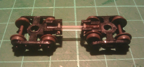
By using a shorter fixed link the gap between the coaches is reduced, as shown below.  This is ideal for connecting locomotives together, particularly if they share a DCC decoder as with my E7 DCC conversion, but it is not so good for lots of coaches.

E7 Coupling 2

For short trains with three coaches or less this would work well but for longer trains with, say ten coaches, it would be very hard to transport them if they were all coupled together.

My second solution is to 3D print a shorter Rapido coupling. The standard Rapido coupling has a shank length of 3.5mm as shown below.

Standard Rapido

So I re-drew the Rapido in a range of lengths decreasing by 1/2mm at a time.

Rapido Replacments

Because I wanted these to be cost-effective they have been designed to be printed in the Black Strong And Flexible material offered by Shapeways.  This has three main advantages over the Frosted Ultra Detail material in that it doesn’t need cleaning on arrival, it is already black so they are ready to use right out of the packet and it’s cheaper.  The BS&F material does have a rough finish but this just helps to make them look a bit more realistic.

The first test prints have arrived from Shapeways and have already been successfully tested with Graham Farish coaches.  Although I ordered the full range of sizes all the coaches we tested worked best with the smallest coupler which has a shank length of only 1.5mm. Using a pair of these couplers, one in each coach, it reduced the gap between the coaches by 4mm which in N gauge is a lot.  Below are the same Graham Farish GOV coaches as pictured before but the pair on the left have the new 3D printed Rapido couplers installed.

Graham Farish Coaches 2

The difference was considerable but a test on a corner was required to check for buffer lock.  We used one of the tightest corners on the club’s N gauge layout for the test and as you can see below it was successful.

Graham Farish GOV Coaches On On Bend 3

Below is a close up on the original Rapido couplings.

Graham Farish GOV Coaches On On Bend 2

And below is a close up on the new 3D printed short Rapido couplings.  You can see that the buffers don’t actually meet.

Graham Farish GOV Coaches On On Bend 1

We also tested the short couplings on some Graham Farish Suburban coaches with equal success.  Again the short couplings are between the left hand pair.

Graham Farish Suburban Coaches 1

And a close up of the 3D printed ones.

Graham Farish Suburban Coaches 2

The 3D printed couplings still need to go through a few more tests and I have also made a few tiny improvements to the design to help with the fit into the Graham Farash coaches.  Once complete I will make them available to buy, and I will also offer them for sale in packs of 20 direct from this site.

One of the tests currently going on is looking to see which length 3D printed couplers work best with an N Gauge HST set, but that will have to wait for another post.

Discovering the Possibilities of Etched Brass

With two locomotive shells already available to buy and several more in the pipeline I have started to look at what can be done to develop them further.  The most frequent request I have had from customers has been for brass handrails so in this post I want to share with you how I’m working on that.

3D printing offers many advantages over other forms of modeling; one of them is the level of detail which can be achieved.  My current locomotive shells and parts have been designed to be printed with a detail level of 0.1mm which for parts such as small vents and door handles is perfect.  But when it comes to self-supporting items, such as handrails, they need to be thicker in order to survive the print and handling process.  Typically a wire part such as a handrail has to be at least 0.8mm in diameter.  Now I know that doesn’t sound a lot but in N scale at 1:160 that is equivalent to 128mm which is very big, and although it is passable, compared to injection molded or wire handrails on a lot of the new ready to run models, it is huge.

The 3D printed handrails on the EMD DD35 pictured below are clearly much larger than the injection molded ones on the Atlas C-628 model pictured underneath.

Locomotive Shells

Atlas C-628 1

The answer lies in brass etching.  Referred to as acid-etching, resist-etching and photo-etching, it’s a process of removing metal in varying layers around a design, leaving behind the composite parts of the model. The main advantage to this is we are dealing with metal which allows it to be incredibly thin and detailed.  The brass metal sheet which I will be working with is only 0.2mm thick and I can etch out parts that are only 0.24mm wide.  This is ideal because I can model handrails at actual scale size.  Although the parts are etched from a flat sheet, once the handrails are painted their ‘squareness’ will be smoothed out.  They can be also designed to be bent in the correct places to achieve the shapes we need.

To begin with I looked at the handrails for the Baldwin DT6-6-2000. There are four side rails and two end rails on this locomotive and I needed to find an efficient and cost-effective way to lay them out so they didn’t take up too much room on the sheet but still had enough metal around them for support.  At this point I realised there would be some spare space on each handrail set so I looked again at the DT6-6-2000 to see what else I could add.  Looking at the photos of the original locomotives working up and down the country I noticed a lot of them had sun shades over the cab windows.  So I have included a set of sun shades with each set of handrails.  Below is the rendered image.

Baldwin DT6-6-2000 Additions Render

I’ve also designed a set of handrails for my EMD DD35 model as pictured below and will be making this set available soon.  The set includes the two main side rails and the four corner rails, there are no sun shades with this locomotive as it has no cab!

EMD DD35 Additions Render

The corner rails also shown below will be etched flat and once removed from the sheet can be bent to form the correct shape.

DD35 Handrails Additions Close Up Render

As you can see from the images above the brass etched parts will form part of my new ‘Additions’ series, which will be available alongside my established range of Shapeways products soon. You’ll have the choice to buy the complete locomotive kit from Shapeways and then if you choose you can add further detail by using the Additions products which will be available direct from this site. I’m striving to make both options as affordable as possible, and at the same time giving you a working, detailed locomotive model to suit your budget and modeling choice.

If you’re interested in being the first to try these brass etched details drop me a message through the Contacts page, I look forward to seeing these in action!

N Scale 2-8-8-2 Y6B & 2-8-8-0 EL5 Replacmet Pilots With Couplers

Last week I shared with you how I added a working Micro-trains coupler to the front of a Rowa 2-8-8-2 Y6B as pictured below; you can find the post here.  The only thing left to do was a running test and this week I’m going to share how it went.Rowa Y6b Finished Pilot N 1

Although the 3D printed replacement pilot fitted perfectly, I had some reservations about the Micro-trains body mount coupler hanging down too low underneath the pilot and preventing the lead wheel set from swinging freely.  This could prevent the locomotive navigating tight bends and turnoughts.

So to test this I took a pair of Rowa Y6B locomotives, and some rolling stock, down to a local model railway club, the Poole and District Model Railway Society, based in Poole, Dorset, who kindly let me use their N scale layout.

As well as having a test track setup for all scales the club also has a reasonably sized N scale layout under construction with a fast double mainline section and a single track branch line. All three lines run in loops through the layout and back to a large storage yard at the rear.  The layout is designed for UK prototype operation and the double track mainline has some lovely sweeping curves, but I was more interested in the branch line.  This was because not only did it have a gradient on a curve but also some very tight curves, particularly for large US outline articulated mallet locomotives, and as the intention was to test the pilot coupling this seemed ideal. Here are the pair working up the grade and around the first curve.


We had to have a couple of goes at this, not because the locomotive struggled but being big US steamers and wider than UK trains the cylinders on the front of the locomotives caught the platform and the guys at the club had to do a quick bit of sanding so the train could get past.


The two locomotives I used for the test run have different makes of DCC decoders installed.  The lead locomotive, DRG&W’s number 3561, has a Hornby R8249 decoder and the second locomotive, Sierra Railroad number 39, has a Digitrax DZ125.  This gave the locomotives different characteristics and having never run the locomotives together before it became clear that the lead locomotive was running faster. This was also a good test to see how the new pilot stood up to the punishment from the lead 2-8-8-2.


The tightest curve on the layout is at the rear where the branch line returns into the yard.  The line at this point is also on a steep downhill gradient.  As you can see from the video below, the new pilot on the front of number 39 had no issues at all going round the bend.


So now the pilots have been thoroughly tested I am happy to release them for sale and you can get them below in five versions…..

One single pilot with a mounting hole for a Z Scale MT body mount coupler.

A pair of pilots with a mounting hole for a Z Scale MT body mount coupler.

One single pilot with a mounting hole for an N Scale MT body mount coupler.

A pair of pilots with a mounting hole for an N Scale MT body mount coupler.

A pair of pilots, one with a mounting hole for an N Scale MT body mount coupler and one with a mounting hole for a Z Scale MT body mount coupler.

Rowa Y6b Finished Pilot N 2

Thankyou to the Poole and District Model Railway Society for use of their layout.

I will have both these locomotives, and maybe a 2-8-8-0 EL5, double heading at my next exhibition pulling some nice long trains.


Double Heading with N Scale 2-8-8-2 Y6Bs

Over the years I have acquired several Y6B mallet 2-8-8-2 steam locomotives made by Rowa.  First produced in 1969 these are beautiful models and run like sewing machines, even by todays standards.  My only issue with them is the motor which, in my opinion, is underpowered for such a large locomotive.  My solution to this is to run two together at the front of a long train, as the railroads often did.  The problem with this is the front coupling is a dummy knuckle coupler and is purely cosmetic.  In this post I wanted to share with you how I overcame this.

These mallet locomotives where first manufactured by MRC/Rowa, then Charmertz/Bemo and finally by Con-Cor/Rivarossi.  They were also released by Con-Cor/Rivarossi as 2-8-8-0 EL-5. Despite minor improvements over the years the main model has stayed the same, here is one sat on the turntable at the roundhouse on Bob Norris layout Somewhere west.

Micro-Trains do offer a conversion kit for this locomotive, No 1048, but all this is is a pair of body mount couplers and you need to cut your own hole in the pilot which can go very wrong.

The pilot on the front, as well as having the coupling, also carries the headlight.  The whole assembly, as shown below, is made up from eight parts which includes the main body, handrails, dummy knuckle coupler, front cylinders and headlight, two plastic valve gear bars, clear plastic light corridor and a metal nut used to bolt it onto the locomotive.  The dummy knuckle coupler is not shown (it was missing on this particular locomotive).

Rowa Y6B Pilot Parts

To remove the pilot you will need to first remove the front set pilot wheels.  With the locomotive upside down remove the plastic plug holding in the front wheel set, this usually has a whisker of plastic running passed the wheel set to give it some springiness, again on this particular model it is missing.

Rowa Y6B Pilot Removal 1

The wheel set then simply lifts out.

Rowa Y6B Pilot Removal 2

The newly exsposed screw holds the pilot in place.Rowa Y6B Pilot Removal 3

Once removed the whole assembly will slide off.

Rowa Y6B Pilot Removal 4

The assembly then comes apart very easily into the seven different parts.  Although I have found out that the very early versions had this assembly glued together and are very reluctant to come apart.

Once I had all the parts separated I set about drawing a 3D model of the main pilot section.  My original intention was to make a replacement part that had a socket to receive a Micro-trains Z scale bodymount coupling.  With the 3D model complete and successfully uploaded to Shapeways I ordered one and as usual within about eight days it arrived on my doorstep.  With this first test print it quickly became apparent that I had incorrectly measured the original because as you can see from the image below the steps are smaller than the original on the left. But this is the reason why I test print everything.

Rowa Y6B Pilot First Print

Although the steps were the wrong size I was still able to experiment with the pilot to see how the Z scale coupler fitted.  Although it did fit well I do find the Z scale couplings really tricky to put together and I felt that it looked too small on such a big locomotive.  You may have also noticed that the cow catcher bars run in a different direction, this is because I used the same 3D model parts I have already drawn for my Atlas 2-8-2 replacement pilots.

So taking all that into account it was back to the drawing board, or at least the laptop.  I first fixed the issue with the steps and I also refined a few other details.  Because I wasn’t keen on the Z scale coupling I created a new version with a pocket to accept the N scale Micro-trains body mount coupling and added horizontal cow catcher bars.

Rowa Pilot Coupling 2

The test prints this time came out fantastic, shown below are the two pilots either side of the original. Z Scale coupling on the left and N scale coupling on the right.

Rowa Y6B Pilots New & Old

To reassemble the pilot, first the handrails need to be secured.  The front two pegs clip into the new pilot and the rear tabs fit under the walkways as shown below.

Rowa Y6B N Pilot Assembly 1

Then the cylinders fit onto the main body and the plastic light strip is inserted into the rear of the headlight.

Rowa Y6B N Pilot Assembly 2

The last part to add was the actual coupling.  This slides in from the front and is secured by a screw.  The standard screw which comes with the body mount couplers is too long and would protrude up through the pilot if left as it is, so I cut it short with a pair of side snips. Please use safety goggles if you are going to do this as the ends fly all over the place.  I left about 2mm (0.078″) of the screw protruding from the coupling, the coupling will need to be installed before the screw is fitted.

Next came the actual test fit onto the locomotive and as you can see below it went well.

Rowa Y6B Pilot Test Fit 2 Rowa Y6B Pilot Test Fit 1

The final test was a coupler height check and for this the locomotive is put onto the track and coupled to a Mocro-trains height gauge.

Rowa Y6B Coupler Hight Check 1 Rowa Y6B Coupler Hight Check 2

This same set of checks were also carried out for the pilot with the Z scale coupling and again, as shown below, it all lined up.

Rowa Y6B Coupler Hight Check 4

Rowa Y6B Coupler Hight Check 3

So using the N scale pilot, my preferred coupling, here are two Rowa Y6Bs coupled together.

Rowa Y6B x2 1 Rowa Y6B x2 2

Now I know that the 3D printed pilots work all that is required is a coat of pain.  I used a simple matt black acrylic paint and the finished locomotive looks like this.

Rowa Y6b Finished Pilot N 1 Rowa Y6b Finished Pilot N 2

Normally when I show a new product I also share with you where you can get it but this week I need to do one more final test before I am happy to release the Rowa Y6B replacement pilots, and that is a full running test on a layout with curves and inclines.  This is to check that the Micro-trains bodymount coupler does not interfere with the leading set of wheels as they are very close.  So in a future post I will have some more pictures, maybe some video and I will let you know where you can purchase your own.


Finishing Santa Fe No. 2601 – A Baldwin DT6-6-2000

Over the last two weeks I have been working on my latest release, the Baldwin DT6-6-2000, in this post I wanted to share with you the finished model and how we did it.

Following on from my last post about this model in which I showed you the test print, I needed to make some more minor changes to the 3D computer model.  In particular there were a few concerns about the thickness of the window frames in the cab.  Although the test print had printed successfully, these parts where incredibly thin and posed the possibility that they could get damaged in the shipping and handling process. This has now been improved in the 3D model. Also, and I had to laugh when I did this, the engineers cap had the same problem.  He has now been outfitted in much sturdier attire.

With the model successfully printable and available to all it was time to turn my attention to finishing the test print and making it into a proper model.   For this I once again handed the model over to Bob Norris to paint and decal.

As with all my models which are printed in the FUD (Frosted Ultra Detail) material it needed to be cleaned to remove the waxy residue left over from the print process.  You can read more about doing this in my FAQ section.

Once cleaned, as you can see from the photos below, a lot more of the detail becomes visible.  These photos were taken not long after the model was removed from the Goo Gone, it will turn totally white and opaque in about 24 hours.

DT6-6-2000 Cleaned 1 DT6-6-2000 Cleaned 2

The body shell and truck side frames were then sprayed black all over, the intention was to use decals to get the silver tiger stripe look.

DT6-6-2000 in Black

This is where we had a bit of a shock because the decals we had were not silver but black.  This meant that the areas intended to be striped needed to be painted silver.

DT6-6-2000 With Silver

The silver was brush painted and when dry the decals were applied.

DT6-6-2000 Strip Decal 1 DT6-6-2000 Strip Decal 2

Microscale 60-247 is a set of decals which are silver and will work for this model without the need to paint any silver, you can find them here.

The engineer and cab interior was also hand painted and glued inside the shell.  He is very small but he is visible through the window. A lot of the photographs of these engines show the windows open so one of the verticals has been removed to represent this.

DT6-6-2000 Driver

To add glazing to the unopened windows and doors Bob used Micoscale’s Kristal Klear.  This is a great product which quickly allows you to add small window glazing to models.  Another alternative would be to use small rectangles of clear plastic sheet and glue them to the inside of the shell.  The rear of the doors and windows are recessed to help with this.

With all the decals applied and the shell just about finished it was time to look at lighting the engine.  Because the chassis came from an Atlas C-628 the LEDs on the circuit board are shorter than the shell to allow for the cab.  The light is transferred to the headlights via a clear plastic path, similar to a fiber optic cable.  My 3D printed shells don’t have this clear plastic path.  But the inside of the headlights have a pilot hole ready incase you want to add lights.  This can be done very easily using either the original circuit board for DC (Direct Current) or a drop in decoder for DCC (Digital Command Control).

This particular model will be DCC and the original circuit board has been replaced with a Digitrax decoder, model number DN163A0.  Before the decoder was fitted Bob replaced the LEDs with longer ones as pictured below.  Then he drilled through the headlights in the shell, the LEDs on the decoder line up with the headlights in the shell.

DT6-6-2000 LEDs

Another alternative would be to use the Digitrax sound decoder SDN144A0.  Because the chassis is recessed, as shown on the left of the above photo, there is more than enough room for the speaker and capacitor, although you may need to extend the wires to make it all fit.

Once the main body was painted the handrails were added.  I have supplied handrails with all the shells but they are not attached in their final location.  This gives the modeller the choice of using finer brass wire or an equivalent to getter a smaller rail detail and it also makes it easier to paint the shell.  For this model Bob used the supplied printed handrails.  They come inside the shell on a sprue for protection and need to be cut out, this is a delicate process as they are very fragile and brittle. The sprue also braces the shell throughout the print and cleaning process at the Shapeways factory.   Once the sprue has been removed all 6 handrail sections can be removed and painted.  I have supplied very small dimples or holes in the shell to act as locators for the handrails.  These also act as guides to help if you are adding your own wire handrails.  Bob glued the painted handrails onto the shell, here is what they look like.

DT6-6-2000 WIP 1 DT6-6-2000 WIP 3 DT6-6-2000 WIP 5

To complete the model bob used decals from the Microscale sheet 60-247 to add the numbers and AT&SF road markings, he then sealed the paint and decals with a coat of Testers Dulcote.  The shell was fitted back onto the chassis and here are the results.

DT6-6-2000 Finished 1 DT6-6-2000 Finished 2 DT6-6-2000 Finished 3 DT6-6-2000 Finished 5 DT6-6-2000 Finished 6 DT6-6-2000 Finished 7 DT6-6-2000 Finished 9

These shots were taken on Bob’s DC layout so capturing it with the lights on is not so easy but as you can see from he action shot below, they do work

DT6-6-2000 Finished 4

So there we have AT&SF No. 2601, a Baldwin DT6-6-2000 in N Scale.  You can get your own here or we can provide ‘Ready to Run’ models upon request.  In a later post I will share some videos of this locomotive running, maybe teamed up with AT&SF No. 2602.