Adding Lights to a HO Scale Union Pacific Water Tender Part 2

Two weeks ago I shared with you the first part of this post about adding working lights to some of my HO Scale Union Pacific excursion train water tenders.  You can find the post here.  In this week’s post I will share with you the next step.

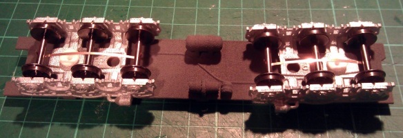
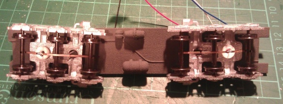
At the end of the previous post I had gotten as far as adding the power pickups to the 3D printed trucks and installing the DCC decoder as you can see in the image below.

HO UP Tender Power Pickup 17

The original idea was to simply hook the white and blue wires up to an LED which was mounted inside the tender shell.  Below you can see the chassis with the LED fitted and working.  I have also added some weight to the chassis which greatly improves the power pickup.  The weight is off-center to avoid the baffle in the center of the tender shell.

HO UP Tender Chassis Switch 7

However upon testing the system I discovered a small problem.  Because the DCC decoder I had selected is a function only decoder, that is to say it has no motor controls, it works well when run on a DCC layout but will not function properly on a DC layout.  This is because a function only decoder doesn’t recognise direction.  A regular DCC decoder will recognise forwards and backwards, switching on the relevant wires to turn on the correct lights.  A function only decoder will simply respond to function key commands.  In the case of the Digitrax TL1 that I have used; F1 will turn the white wire on and off.  When the tender is running on a DCC layout the operator can consist the tender with the locomotive, then when they push the F1 button the tender headlight will come on as required.  But under DC control the headlight will only continue to do whatever the last command was under DCC control.  For example if the light was lit when running on DCC, the light will remain lit in DC irrelevant of direction and cannot be turned off.

As these two tenders are wanted for both DC and DCC operation I will need to come up with another solution.  One option would be to replace the function only decoder with a full motor decoder.  That way it would respond to directional control in both DC and DCC but there would still be the risk of it being removed from the DCC layout with the light off, then it would not work on the DC layout.  Also full motor decoders are more expensive.  A simpler option that I have decided to use is to add a switch to the underside of the tender chassis which will allow the operator to switch the tender from DCC to DC control.  That way the function decoders that have already be purchased will not be wasted.

The type of switch required is a double pole double throw toggle switch.  Double pole means that it can switch two separate wires at the same time; in this case positive and negative.  Double throw means rather than simply on and off it switches each pole from one input to another; in this case DCC power to DC power.

As I described in part one of this post each truck picks up power from a different rail.  Irrelevant to whether it is a DCC or DC layout, one rail is treated as positive and one as negative.  At this point the two power wires need to be divided so that power goes to the DCC decoder and to one side of the switch.  The output from the DCC decoder will then go to the other side of the switch.  From the middle of the switch will come the two wires that feed the LED.  When the switch is set to the DCC side the system will operate as it did before, responding to the F1 command on a DCC system.  With the switch set to the DC side the power will bypass the DCC decoder and go directly into the LED.  Because and LED is a diode, which means power can only pass through in one direction, the light will only come on when the train is moving in the direction the light is facing.

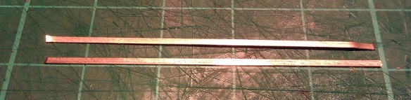
To find the right DPDT toggle switch I had to look at the available space on the chassis.  Although there is a lot of room inside the tender itself, there is not a lot under the chassis and I did not want something huge sticking out that looked unsightly or might foul things like turnouts or crossings.  A standard DPDT toggle switche would be simply too big, as would a sub miniature one; but an ultra miniature one would work well.  Below is an ultra miniature switch next to a miniature one.

DPDT Swiches

The switch will be mounted to one side near the center of the chassis.  That way there is no chance of it interfering with the swing of the trucks.

HO UP Tender Chassis Switch 1

Although this switch is very small the lever that projects out is still too long so I cut about two-thirds of this off with a disc cutting tool and filed the edges to remove any sharp bits. It is now fairly inconspicuous under the chassis.

HO UP Tender Chassis Switch 2

A small corner of the air tank also had to be cut off to allow the toggle switch nut to be fitted but this will not be visible when the tender is on the track.  The switch will also be painted gray to match the chassis helping it blend in.

HO UP Tender Chassis Switch 8

Next the switch needs to be wired up.  The red and black wires from the trucks go to the two terminals on the far side.  The DCC decoder is then also connected to the same terminals.  This is where the power is split.  The output from the DCC decoder, the white and blue wires, are connected to the near side terminals.  With DCC decoders the blue wire is the common function wire which is positive. Therefore it needs to be connected to the switch on the same side or pole as the red wire.  If the light was powered by a regular bulb this would not make a difference but because LEDs are diodes the polarity of the wires is important.

HO UP Tender Chassis Switch 3

Next the LED wires are connected to the two center terminals as shown below.

HO UP Tender Chassis Switch 4

Often DPDT toggle switches have three positions, the middle being off.  This can be useful as it ensures there is no chance of a short as the switch is thrown. However the ultra miniature switches only have two positions but as the tender needs to be removed from the track to throw the switch this is not a problem.

The LED I am using is a 2mm lighthouse style with a warm white color.  Regular white LEDs are often too bright and give a very cold light.  I should also point out that it is necessary to use a resistor with every LED otherwise they will draw too much power and blow immediately.  Below is a comparison between an ordinary 5mm LED and the 2mm lighthouse LED.

HO UP Tender Chassis Switch LED

The light these warm white LEDs give off is perfect for recreating locomotive headlights as you can see from the images below.  For these photos the headlight has not been properly secured so it is pointing up a bit.  I need to finish the shell and add all the decals before I can fix the headlight on properly.

HO UP Tender Chassis Switch 6

Taking photographs in the dark is not the easiest thing to do but below is a shot of the tender in low light, as you can see the headlight gives a nice beam.

HO UP Tender Chassis Switch 5

In next week’s post I will share with you the final stage of fitting the LED into the shell.  I will have also finished the shells, completing the tenders.

Replacement N Scale Horns Part 2

A few weeks ago I shared with you my designs for some N Scale 3D printed replacement horns for some of my locomotives, you can find the post here.  In this post I wanted to share with you some of the results and let you know where you can get some from.

To start with I have two types of horns available, both are three chime horns.  One has all three chimes facing the same way, the other has one of the smaller chimes reversed.  In the rendering below you can see both types.

N Scale Horns Render

My Type 3-1 horn is the set with all three chimes facing forwards and it has been used on my RT-624 locomotive kit.  Below is a photo of two of the Type 3-1 horns giving a sense of the scale.

RT-624 XHD First Print 8

Below is a photo taken by Chris Broughton of his Pennsy RT-624 on the work bench.  You can see the horns to the right of the cab under the train phone antenna.

PPR RT-624 (Chris Broughton) 5

Here is Chris’ finished locomotive.

PRR RT-624 8355(Chris Broughton) 3

My Type 3-2 horn is the other set with the reversed chime, below is an image of a set of Type 3-2 horns fitted to a Kato SD40-2 that had lost its original horns somewhere down the line.

Horn Type 2 on SD40-2 8

The locomotive really is not that pink in colour, that is just a side effect of the lamps at my work bench.  Below are some photos of the SD40-2 with its new horns doing what it does best.

Horn Type 2 on SD40-2 1 Horn Type 2 on SD40-2 2 Horn Type 2 on SD40-2 3 Horn Type 2 on SD40-2 4 Horn Type 2 on SD40-2 5 Horn Type 2 on SD40-2 6 Horn Type 2 on SD40-2 7

To make the horns cost viable I am making them available in packs. The first pack available will contain both Type 3-1 & Type 3-2 horns, plus a mirrored set of both.  There will be twelve horns in total; three of each.  Each horn will be on sprue bar with its mirrored opposite and will need to be cut free, below is a rendering of a Type 3-2 horn with its mirrored twin on the sprue.

Type 2 Horns with Mirrored Version

You can find the pack of 12 horns here.

If you have a specific horn that you require for a locomotive in N Scale, or any other Scale, please contact me through the Contact page and I can make one available for you.

In next week’s post I hope to get back to completing the HO set of tenders with working lights that I started showing you last week.

Adding Lights to a HO Scale Union Pacific Water Tender Part 1

My 3D printed tender kits for Union Pacific’s excursion trains are now available in several scales.  The kits come with 3D printed headlights, or more correctly, backup lights.  In this post I will share with you how I finished a set of HO tenders with working backup lights.

Only one headlight will work on each tender.  This will be the one at the rear and will only come on when the locomotive and tender or tenders are backing up.  The headlight on the front of the tenders will be a dummy.  I need the lights to work in both DC and DCC modes.  To do this I am going to use Digitrax single function decoder TL1.  This simple decoder only has four wires, two which go to the track and two which go to the lamp in the headlight.

The kit, as shown below, has several parts printed in two different materials.  All the high detail parts can be printed in Shapeways Frosted Detail or Frosted Ultra Detail materials.  The low detail parts such as the chassis are printed in Shapeways White Strong & Flexible material.  When the kit arrives from Shapeways the headlights are attached to the loop that joins the ladders together; in the image below I have cut the loop and removed the ladders.

HO UP Tender Parts

The first thing to do is to work out how to collect power from the rails and get it into the body of the tender.  To do this I am going to use metal wheels with axle wipers.  One truck will collect power from the left rail, the other will collect from the right rail.

The trucks that come with the kit, as pictured below, are designed to take Proto 2000 33″ metal wheels from Walthers.  The trucks are fixed to the chassis with 3D printed bolster pins that simply push in.

HO UP Tender Power Pickup 1

Although the Proto 2000 wheel sets have metal wheels the axle is made from plastic which is no use for picking up power.  A good alternative are Intermountain’s 33″ wheel sets.  These have metal wheels and a metal axle and one of the wheels is electrically isolated from the axle.  However using these does cause a problem.  The point to point dimension of the Intermountain wheel sets is slighty smaller than the Proto 2000 ones.  This means that the wheel sets will fall out when the tender is picked up.  To solve this I have used small off cuts of solid copper wire superglued into the V grove below the axle sockets as pictured below.  When the trucks are the right way up and sat on the track the wheel set axles will be resting against the top of the axle socket; the copper wire simply stops them from falling out.

HO UP Tender Power Pickup 2

The next issue is how to transfer the power from the axle wipers up into the tender.  A flexible wire is the easiest way but the position of the wire can cause complications.  The further away from the bolster pin the wire is the more it will rotate as the tender runs around a bend. A crescent shape will need to be cut into the chassis to receive the wire.  The maximum radius that the tender will be able to negotiate will depend on the size of the crescent.  An alternative to this is to run the flexible wire up through the bolster pin.  Because the HO kit is a scaled up version of the N Scale kit the bolster pins are quite big.

HO UP Tender Power Pickup 3

I used a small drill bit in a pin vice to drill a pilot hole through the bolster pin.  The head of the bolster pin was printed with a hole through the thicker section to reduce material, which helps guide the drill through squarely.

HO UP Tender Power Pickup 4

Then I fitted the bolster pins into the chassis and used the larger drill bit to drill all the way through.  The size of the drill bit depends on the wire and wants to be just a bit bigger to allow the wire to pass through easily.HO UP Tender Power Pickup 5

The bolster pins were then removed and any swarf was removed from the holes.

HO UP Tender Power Pickup 6

Next come the fitting of the wheel sets.  It is very important to note their orientation.  In the image below the wheel set on the left is electrically connected to the wheel at the top.  The wheel set on the right is electrically connected to the wheel at the bottom, you can see the plastic isolator where the top wheel joins the axle.

HO UP Tender Power Pickup 7

It is important to get all the axles in the same truck orientated the same way around. otherwise the truck will cause an electrical short.  Because the trucks are the same, just rotated 180° you can insert the wheel sets the same way round in both, then when they are fitted to the tender one will pick up on one rail and one will pick up in the other.HO UP Tender Power Pickup 8

The trucks can now be fitted to the chassis as shown below.

HO UP Tender Power Pickup 9

Doing a rolling test at this stage is a good idea to ensure the wheels run freely.

HO UP Tender Power Pickup 10

To make the axle wipers I have used 1mm wide phosphor bronze strips about 45mm (1.771″) long.

HO UP Tender Power Pickup 11

The wiper strip is pushed through the axles.  It goes under the two outer axles and on top of the middle one.  That way it will utilize all three axles to collect power.

HO UP Tender Power Pickup 12

Then using my fingers I bent the ends of the wiper strip around the outer axles.  This will stop the strip from rolling out and moving as I work on it..

HO UP Tender Power Pickup 13

Using my soldering iron I tinned up the strip just above the hole in the bolster pin.

HO UP Tender Power Pickup 14

Then one of the wires from the DCC decoder was fed through the chassis and bolster pin.  A small section at the end of the wire was striped back and tinned with solder.  The end was then bent over by 90°.  In the image below this has been done to the black wire.

HO UP Tender Power Pickup 15

This hook can then be positioned over the tinned wiper strip and with a quick touch of the soldering iron they can be joined.

HO UP Tender Power Pickup 16 HO UP Tender Power Pickup 17

There is a risk with this configuration that the axle wiper will rotate and run diagonally across the axles.  If the wiper strip touched a wheel that is isolated from the axle it will cause a short.  There are two things that can be done to prevent this.

The first is to remove one of the end wheel sets, this will cause the wiper strip to fall out.  If you gently roll the ends of the wiper strip around a bit further between your fingers and then refit the wheel set not only will it be a tighter fit almost preventing the wiper strip from going diagonally, it should also improve the contact with the axles thereby improving the power pickup.  This can add drag to the wheel sets and you should check that the tender still rolls well once this has been done.

The second is to add a guide which the wiper strip will run between.  To do this I used some of the same solid copper wire I used in the V slots of the trucks.  I bent the wire into the shape shown below.HO UP Tender Power Pickup 18

This bent wire shape fits down through the second hole in the truck frame as shown below.  Once I was happy with the fit they were superglued in place .

HO UP Tender Power Pickup 19

The forked ends protrude down on either side of the wiper strip giving some room to move but preventing it from going diagonal.  The other end is held in place by the wire coming through the bolster pin.HO UP Tender Power Pickup 20

Below is a close up of a finished truck with a fixed axle wiper collecting power from all three axles.

HO UP Tender Power Pickup 21

This now completes the tender chassis, in next week’s post I will show you how the working tender headlights were fitted and how the tenders were finished.

Replacement N Scale Horns

As a lot of my N Scale diesel locomotives are older and have been acquired from train shows over the years, a few of them have, at some point, lost some of their detailed parts; particularly their horns.  So every now and then as I am ordering parts for other projects I have been drawing up horns and adding them to the order so that I can repair my fleet.

Below is a rendering of some horns originally drawn for the Baldwin RT-624.  The horn on the left is the one which comes with the RT-624 kit.  I rotated one of the cones to make a bi-directional set to use on another switching locomotive which has been with out horns for a while.

N Scale Horns Render

Each set has a peg in the bottom so it can easily be inserted into a hole in the locomotive shell.

Although these are very small they printed very well in Shapeways’ Frosted Ultra Detail material.  I did have to make a few sacrifices with size in order to meet the minimum printable thickness but overall I am happy with the result.

N Scale Horns 1 N Scale Horns 2

Once the last of the powdery residue has been removed and they are sprayed the right colour I will fit some to my locomotives.  Below is a photo of one sat on an atlas GP loco to give a size comparison, I think they will be just fine.

N Scale Horns 3

The next set of horns I need is for a Life-Like Alco FA2.  This are single cone horns and I will be drawing a set and adding it into my next order.  Given the size of a single horn I will probably need to join them together for the print processes.  Then they can be cut apart and fitted into the holes in the FA2 cab roof.

Once I get a good selection of horns drawn and printed I will make them available too buy through Shapeways in packs.

Replacement Eccentric Rods for a MRC/Rowa N Scale 2-8-4

As well as the complete locomotive shells and bigger kits I also use 3D printing to make replacement parts for a whole number of repairs and improvements to my trains. In this post I will share with you my 3D design to replace a missing part from an old MRC/Rowa 2-8-4 steam locomotive.

The 2-8-4 Berkshire locomotive, pictured below, was made by Rowa who were a German manufacturer of European model trains. In 1969 they released this US model along with their impressive 2-8-8-2 Y6b. Both these models were imported to the US and sold by Model Rectifier Corp (MRC) and were very popular as they were and still are good locomotives. Compared to today’s offerings they are a little bit dated and smooth running at slow speed can be hard to achieve. There is no DCC readiness but a conversion is not tricky to do and they are still good-looking models; and if still running well are also reasonably good pullers.

Rowa 2-8-4 Berk Acc Rod 1

Around 1977 Rivarossi acquired the tooling for this model and re-released it using Con-Cor as the importer.   Rivarossi made some improvements to the locomotive; the relevant one to this post was to the side rods and valve gear of the locomotive. Rowa’s locomotive had plastic side rods and valve gear which were colored gray. Rivarossi changed this to metal.

My 2-8-4 is one of the early ones made by Rowa with the plastic side rods and valve gear. As I have often seen when looking at second-hand Rowa 2-8-4 models the eccentric rod was missing from one side of mine. Below you can see one side with the eccentric rod and one side without.

Rowa 2-8-4 Berk Acc Rod 3

Rowa 2-8-4 Berk Acc Rod 2

The eccentric rod drives the valve gear in the top of the locomotive steam cylinders. This opens and closes the valves at the right position to allow steam to push the main rod in and out of the piston chamber. Although the eccentric rod has no real effect on the running of this model locomotive it is an important cosmetic part; the real locomotive could not operate without it and I would like to see this locomotive working properly.

The original plastic eccentric rod simply clipped into the C shaped mounts you can see in the photo above. There is one offset on the third driver, where the main rod connects to the side rod. The other is between the first and second driver just under the bell crank. The plastic eccentric rod has pins on the rear that fit into the C shaped mounts. It fits with a snap and the C shape holds it in place but allows it to rotate. Below is one of the eccentric rods removed from one of my other Rowa 2-8-4s.

Rowa 2-8-4 Berk Acc Rod 4 Rowa 2-8-4 Berk Acc Rod 5 Rowa 2-8-4 Berk Acc Rod 6

I think it’s because the eccentric rods can snap out so easily that so many are missing from the secondhand models.

This was a very quick 3D model to draw and I was able to keep the part sizes the same as the original Rowa part without going below the recommended sizes for the material I want to use.

Oddly enough the pins on the rear of the eccentric rod are not in the center of the rounded ends but offset towards the ends as you can see from the rendering below.

MRC Berkshire 2-8-4 Eccentric Rod Render

These will be test printed in Shapeways Frosted Ultra Detail material which will give the best detail and should also ensure a smooth surface on the rod. As these parts are very small they can’t be printed individually so when I make them available it will be pairs.

These should be going to test print soon along with other small parts like the O Scale F9 gears from last week’s post. Once I get them I will share with you the results as well as some video of the new 3D printed eccentric rods powering my Rowa 2-8-4 Berkshire.