A Replacment Pilot for A Con-Cor Galloping Goose

As promised in last week’s post I have a replacement part to share with you for one of Rio Grande Southern’s famous pieces of rolling stock.

The ‘Galloping Goose’ is one of those items that Con-Cor made, and made very well, which you just fall in love with. Even though the prototype was a narrow gauge rail car and this model runs on standard N Scale track it’s a great piece of modeling, particularly because it’s so small.

Galoping Goose Pilot 1

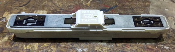
This ‘Goose’ is very highly detailed and on the front is the classic cow catcher or pilot and it’s this part that I was asked to make by a fellow modeller who’s missing one.

Galoping Goose Pilot 2

As supplied by Con-Cor the pilot comes in two forms; as shown above and with a snow plow, shown below.

Galoping Goose Pilot 3

The plow is a separate part which simply clips onto the pilot.

Galoping Goose Pilot 4

For this replacement part only the pilot section was required, so I removed the plow and measured up the pilot.  The verticals are very thin on the original injection-molded part so the replacement can’t be exactly the same: having such thin 3D printed parts would be very weak.  This can be overcome by increasing the depth of the verticals and making the sections larger, however all the main visible areas and mounting points will look correct.  As usual I produced a rendered image of the 3D model and below you can see the pilot from several angles.

N Scale Goose Pilot Render 3

The two pegs protruding horizontally from the cross beam are all that hold the pilot to the front of the ‘Goose’.  The two bars that slope upwards are purely cosmetic although on the real thing they are a part of the pilot mounting.

I will be ordering a test pice of this pilot in the next week or so. However you can order one already from the Shapeways site.

It is available as a single pilot here.

Or as a pack of two here.

The pilot has been designed to be printed in Shapeways Frosted Ultra Detail (FUD) and Frosted Extreme Detail (FXD) materials so the best detail can be obtained; after all, this part is only 10mm wide and 6mm high.

I can also make the snow plow available if anybody wants one although I expect it will not be a separate part but an entire replacement pilot with the plow permanently attached.

Next week I’ll have another small replacement part to share with you which will help step things up a gear.

Replacement Graham Farish Bolster Pins

With all my recent time being focused on my C-855 project, several of the smaller jobs have been overshadowed, but not forgotten.  So in the next few posts I’m going to share with you some of some of the small 3D printed parts that I have been asked to do over the last few months.

To start with in this week’s post we have some replacement N Gauge bolster pins for Graham Farish coaches and bogied wagons.  The bolster pin, sometimes refered to as a truck pin or bogie pin, holds the truck or bogie onto the chassis.  The pin allows it to rotate and navigate corners.  The pin has to be a tight fit into the chassis so it won’t fall out but still allow the truck or bogie to rotate freely.  This is achieved through the hole in the chassis being exactly the same size as the pin.  This creates a friction grip as the pin is pushed into the hole.   The friction grip is a stronger force than normal gravity and vibration can provide to remove it.

As always, I start with a 3D computer model.  This model is simple but it was important to get the measurements accurate so the peg won’t be too tight or too loose in the chassis hole.

Replacement Graham Farish Bolster Pins 7

Because these will be printed in Shapeways’ Black Strong & Flexible material and they charge by the part, I have arranged twenty pegs all connected to one sprue.

Replacement Graham Farish Bolster Pins 8

The printed parts came out as expected; I had already removed two before I remembered to take a photo.

Replacement Graham Farish Bolster Pins 1

Below are a pair of the injection molded pegs as supplied by Graham Farish.

Replacement Graham Farish Bolster Pins 2

And here is a photo of one of my 3D printed pegs next to an original.

Replacement Graham Farish Bolster Pins 6

The Black Strong & Flexible material does have a grainy finish but this is of little consequence as the pin is never seen once the rolling stock is on the track.  The material is also fairly flexible, as the name suggests, and this helps with ensuring a good fit into the chassis hole.

As a test, the pegs on a standard Graham Farish Mk1 coach were swapped out for the new 3D printed ones, which fitted perfectly.

Replacement Graham Farish Bolster Pins 3

The injection molded original has the same finish as the truck; as you can see below.

Replacement Graham Farish Bolster Pins 5

The 3D printed peg, apart from the finish, is exactly the same.  You can see from the shadow there is a slight gap between the bogie or truck and the head of the peg.  It’s the gap that allows the bogie or truck to move.  If you look closely you can see that the couplings have also been replaced with my 3D printed short Rapido replacements.

Replacement Graham Farish Bolster Pins 4

The pack of 20 replacement Graham Farish bolster pins are available here.

In next week’s post I will have a replacement 3D printed part to share with you for one of Rio Grande Southern’s more famous pieces of rolling stock.

An Alco C-855B Chassis For N Scale

In last week’s post I said I was going to share with you the test fitting of the N Scale Alco C-855B body onto the modified chassis and that’s exactly what this week’s post will be about.

The C-855B is basically a C-855 without a cab. It’s exactly the same length and all the trucks and parts are in the same place.  However, as there is no wide cab this section at the front end of the chassis will need to be modified.

The donor chassis is from a Con-Cor U50 or Turbine and has been extended using my 3D printed stainless steel parts. You can read more about that here.

The rear of the chassis doesn’t need any modifications. The front needs to be cut to resemble the rear.

In the image below you can see the top section of the extended chassis.  I’ve also started to modify it by cutting off the front right lug which used to fit inside the cab area.

C-855B Chassis 1

In this close up you can see I’ve cut it so it tapers in very slightly from the side of the chassis.  This helps with the fit.

C-855B Chassis 2

Repeating the same cut on the left hand side will finish off the top section.  To make these cuts I simply used a cutting disc in a Dremel-style tool.

C-855B Chassis 3

The bottom section will require a bit more work.  Again you can see in the image below I’ve already done the right hand side and I am working in the left. To get the cuts in the right place I fixed the top and bottom halves of the chassis together and marked the bottom with a pencil.  The cuts should line through vertically.

C-855B Chassis 4

Using the cutting disk I cut along the top of the chassis following the same line as I did with the top section which was marked in pencil.  You only need to go down as far as the lower flat area.  Then, cutting horizontally, I came in from the side.

C-855B Chassis 5

When you are almost through it should look something like this.

C-855B Chassis 6

Once the unwanted section has been cut out the area can be cleaned with a file.

C-855B Chassis 7

The last section to remove is part of the front.   Again I marked the cut line with a pencil after fixing the two halves together and then used the cutting disk to slice in from the top.

C-855B Chassis 9

The last cut comes in horizontally to remove the unwanted section.

C-855B Chassis 10

The chassis is then assembled and is ready for a test fit.

C-855B Chassis 11

I found that my chassis was about 0.5mm too long for the shell; this might be caused by a slight shrinkage in the 3D print when it first cooled or too much glue between the chassis extenders and the original bits.  The shell should be a nice fit and shouldnt need to be forced. This was easily fixed by cutting a thin slice off the front as you can see below.

C-855B Chassis 12

The shell and fuel tank then fitted perfectly over the chassis.

C-855B Chassis 13

It’s important to make sure the chassis is fitted in the correct way round.  Both the chassis extender parts have arrows which point forwards and on the C-855B the front is the plainer of the two ends.  In the photo below this is on the left.

C-855B Chassis 14

All that is left to do now is to have it painted, fit the last bits of brass and add a DCC chip and it will be ready to join its C-855 companions to complete the trio.

C-855B Chassis 15

This has been a fun project to work on even though it has taken a long time.  I’m looking forward to seeing all three working hard uphill on the layout ‘Somewhere West’.

Etched Brass Additions for an N Scale C-855B

This week’s post will be short as I’ve had very little modeling time due to the unfortunate demise of my much-loved motorcycle and the search for a replacement.  However there is good news; not only have I found another bike but the C-855B brass Additions have arrived and they look great.

C-855B brass Additions

The C-855B brass Additions are very similar to the C-855 set, although there are no windscreen wipers or sun shades.  There are also less grab irons, but two larger end handrails have been added as well as the extra end handrail.  These are the three parts on the left hand side.

For those that have pre-ordered your C-855B brass Additions, they have now been posted and should be with you very soon.  I have several sets in stock and they can be ordered here. Alternatively you can contact me through the contact page.

As I said, time has been short, so I haven”t test fitted the C-855B body onto an extended chassis yet but I will have it all done for next week’s post.  The body’s also going into the paint shop so there’s a small chance I might have the whole set finished and ready to share with you then.

Adding Window Glazing and Wipers to the Alco C-855

Last week I showed you how I added lighting to my C-855s.  The final details to add to the locos are the window glazing, and to keep those clean, the windscreen wipers.  In this post I will share with you what I did.

The glazing is fairly simple.  A use clear plastic sheet which can be cut with scissors or a sharp craft knife.

C-855 Glazing 1

I designed the inside if the window areas to be flat so the plastic need only be larger than the window and glued in place. For the front four windows I use one strip of plastic measuring 18mm by 6mm.

C-855 Glazing 2

For the two side windows you will need one square piece each measuring 6mm by 6mm.

C-855 Glazing 3And don’t forget the windows in the doors, that piece needs to be 5mm by 3mm.

Before you attempt to glue anything test fit each window with a pair of tweezers to make sure it fits.  This also helps to work out the best angle to put them in at because it’s a bit tight on maneuvering room.

I like to use Gel Control superglue made by Loctite.  Not only does this superglue give you about 12-15 seconds before it sets it also doesn’t run allowing you to get it where you need it.  However if you simply try to put it around the window frame or on the actual plastic with the nozzle it wont go well.  You will get two much and in the wrong place.  It’s best to put a drop into a bit of scrap paper, then use a toothpick to put an even smaller drop on the window frame.  You don’t need much as it will spread out under the plastic.  Also you don’t need to go all the way around, two or three places will be fine.  The more glue you put on the higher the risk of it spreading out or smearing over the part you want to be the window and that doesn’t look so good.

Once all the windows are in place, and stuck, its time to add the windscreen wipers.  I sprayed the brass parts before removing any from the fret, it’s much easier that way.  The wipers are in pairs and handed.  Looking from the front of the fret, the wipers below are for the right hand side, the longer one is for the outer window.

C-855 Wipers 1

Once the wiper is removed you will notice a small half etch on the back of the arm.

C-855 Wipers 3

This is where you bend the arm to fit it into the hole in the shell above the window.

C-855 Wipers 6

Then it’s simply a matter of adding some glue to the arm and pushing it into the hole.  As the glue sets you have a few seconds to rotate the arm, the normal resting place is on the out side of each window.

C-855 Wipers 7

The last thing I wanted to share with you is a little fix to solve a problem that has been annoying me.  Because the fuel tank on the C-855 is sloped on the under side, not square like the Turbine or U50, the peg on the back of the trucks has to be cut off.  When the loco is on the tracks this causes no problem at all but if you pick up the loco the trucks swing out and hit the ladders.  It also makes it a pain to put back onto the track.

To solve this I have used a piece of plastic sprew from an old kit.  Any thing of a similar size will do.  In the shot below you can see the lug protruding out of the back of the truck with out its peg.

C-855 Truck Swing 1

I simply glued a short section of the plastic onto the top of the lug.  This will still allow the trucks to move freely but wont allow it to swivel out.

C-855 Truck Swing 3

In order to get the truck in without unscrewing the chassis you can simply unscrew the truck and separate it from the geared section.

C-855 Truck Swing 2

Once everything is reassembled the loco is ready for service.

Finished Alco C-855

And just as the C-855 cab units were completed the postman delivered the next bit.  Here is the 3D printed C-855B kit in its raw state. The plastic parts will shortly be going into their cleaning bath and later this week will be off to the painters.

C-855B Kit - Raw

The C-855B brass Additions have been ordered and will also be arriving this week so hopefully I will be able to show a bit more in next weeks post.