Small Steps Forward and New Releases on the Horizon

This week’s post will be short as it’s been a busy week.  I’ve made some progress with the UP rotary snow plow as you can see in the image below.  To read more about this project you can find the first post here.

As you can see a lot of the brass details have been modelled such as the grab irons and roof handrails.  Unlike most locomotives or freight cars, which have one point of access to the roof for maintenance, this rotary snow plow is covered in them.  So far there are 86 separate brass parts and there are many more to add.  But I know how much we, as modelers, love detail so if it’s right, it’s worth it.

On a different note; if anybody went to Amherst Railway Society Show, in West Springfield, Massachusetts, over the weekend you may have seen The Scale Architect’s stand with some of their new releases.  For those that couldn’t make it the new release which interested me the most was the ‘Naval Gun Barrel and F22 flatcars’.

This 3D printed kit will be available in March 2018.  Now I wonder who could have drawn that?!  A bit closer to the release date I’ll have some more info and pictures to share with you about it.

Next week I plan to get back to the UP rotary snow plow and I may even have the chassis worked out.

Union Pacific Rotary Snow Plow 900081 – Part 2

In this week’s post, as promised last week, I’m going to share with you which chassis I’m planning on using with my UP 900081 Rotary Snow Plow kit.

The reason why I plan on using a commercially available chassis is I want to make it easy to build and have reliable power pickup.  This will make powering the fan on the front much easier.  I can 3D print trucks, add contacts and fit metal wheels but when there’s something already available, which also has a motor and drive shafts, it seems the right way to go.  However the UP 900081, and UP 900082, have two different trucks front and back and the truck spacing doesn’t match anything else so it’s not going to be that easy.

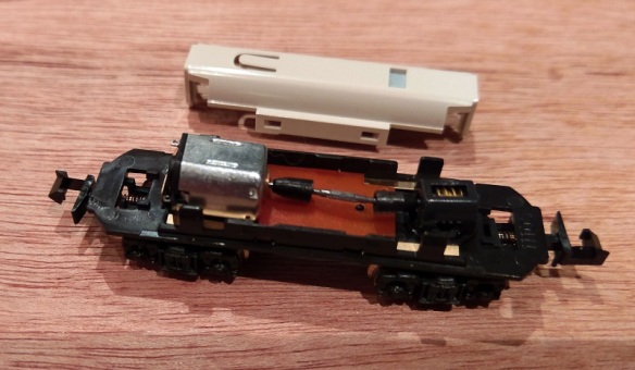
The chassis I’ve chosen as a starting point is made by Kato and can be fitted in to all sorts of things but I think it was designed for Japanese street cars.  The 11-105 is the first of three including 11-106 and 11-107.  All three are the same just with different trucks.

The chassis are fairly cheap and available in lots of places online and in local hobby stores.  Plus they are great runners.

The plastic top is held on by four clips and simply pops off.  Underneath is a motor at one end and a worm gear and truck tower at the other.  There is a drive shaft connecting the two.

This means that only one truck in the chassis is powered by the motor, the other is free running but still picks up power, which is ideal for me.

With the top gear removed from the truck tower the chassis will become free rolling but maintain pickup from all the wheels.  This then allows the fan to be connected to the drive shaft.  This will also take a bit of figuring out as I want to incorporate a reduction gear box which will dramatically reduce the speed of the fan.  Although I intend to convert this to DCC, which will be very easy, simply telling the motor to run really slowly may cause it to stall or seem jerky. Having a gear box will allow the motor to run at a good speed whilst the fan slowly turns.

All that quality pickup will also make it easier to install sound as well, which is an interesting option.

As I said before, there are a few issues with the chassis. Firstly, the truck spacing.  This can be overcome by extending the chassis frame or simply 3D printing a longer one.

Secondly, the trucks themselves are the wrong type, and one doesn’t have enough wheels!  But this too can be overcome and again it will involve some 3D printed parts.  I haven’t decided yet whether to file down the existing side frame and stick on new ones or whether to 3D print a new truck outer section, but as the design develops that will become clear.  At this point you may be asking what is left of the original chassis?  Well, the motor and power pickup, which given the relative cheapness of the chassis is well worth it.

So I have a lot of design and drawing ahead of me on this project and next week hopefully I will have a bit more progress to share with you.

Union Pacific Rotary Snow Plow 900081 – Part 1

In last week’s post I told you about Rotary Snow Plows and my intention to make a model of UP 900081, the largest and most powerful rotary in the US.  You can find the post here.  In this week’s post I’ll go into a bit more detail about what I’m going to do.

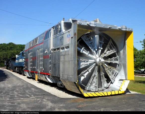
UP 900081, as pictured below, is currently on display at the Museum of Transportation, St. Louis, Missouri, which is really useful as there are now lots of pictures available as reference material.

For my model the main body will be 3D printed in Shapeways FUD or FXD materials simply because to date this produces the best results.  And I’ll be setting the print orientation so the model is printed the right way up. (To see why this is important see my post about 3D print orientation here).

A lot of the surface area on the sides is flat so to help keep it smooth I’ll be making all the grab irons and ladders from etched brass. This has two advantages; firstly, anything sticking out of the side of the print needs support material underneath it in the print process and this can leave a shadow on the surface, and secondly, the etched parts look better. This has worked well on my other locomotives such as my Alco C855 as shown below.

This time I’m also going to include the mesh grills as an etched brass part.  The mesh frame will be 3D printed as part of the shell and a fine mesh will fit in behind.  This will allow you to see inside slightly as with the original.

Other details will also be made from etched brass such as the side window wipers and the unusual rotating windows on the front.  These special windows, shown in the photo below, rotated continuously preventing snow from settling and obstructing the windows.  (Photo of UP 900082 taken at Cheyenne 14th June 2000 by Don Strack),

In this close up on Don’s photo you can clearly see the rotating windows. My 3D printed shell will have a lip behind the window to receive a piece of clear plastic to form the glass and the etched rotating window will sit on top.

The big twelve-foot fan at the front will also be 3D printed but as a separate part as I want this to be able to rotate.  In fact in my model it will be powered. I will have more on how that will be done next week.

Above the fan is the directional chute which will also be a separate part so it can be flipped from left to right.

The trucks on the rotary are not standard either, well, the second one is as it’s recycled truck from a C&O steam tender, but I think the front truck was constructed from parts, making it unique to the rotary.

These will also be 3D printed but they will only be side frames as they will fit onto the chassis which will be a bought in.  Why not 3D print one?  Because I want good reliable power pickup and a motor to drive the fan.  The easiest way to do that is to use a powered chassis that works well.  I will also make a 3D printed chassis and trucks for anybody wants an unpowered version.

Behind the front truck is a snow plow which can be lowered to prevent snow building up under the fuel tank, but this is N Scale so that will be a 3D printed part of the shell.  It will also depend on how the new chassis fits in at that point.

In next week’s post I’ll share with you which chassis I’ll be using and how it will be connected up to the fan (if it arrives in the post in time).  For now I’ll leave you with a quick render of how my 3D model looks so far.

Union Pacific Rotary Snow Plows

Although I have may projects currently working through the system there is always room for one more and this week, given how cold it is and in some parts snowy, it seems the ideal time to start sharing with you my plans for an N Scale Union Pacific rotary snow plow.

This project is at the request of a fellow modeller but it’s one I have been thinking about for a while for myself, I think the rotarys are just fantastic!

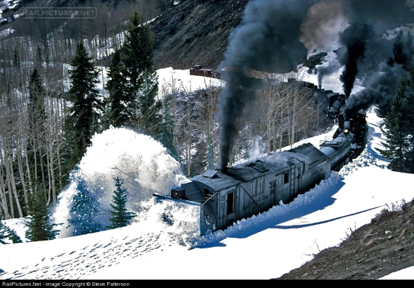
So what are rotary snow plows?  In short they’re the last line of defense against heavy snow fall; when the snow’s falling and regular plows and shovels simply can’t do it the rotarys are called out to cut their way through. And they do literally cut their way through.  In the image below, taken by Steve Patterson and displayed on Railpictures you can see ex-DRGW steam rotary ‘OY’ being pushed by three steam locomotives.

The photo caption says: ‘In an attempt to open its line from winter snows, Cumbres & Toltec Scenic operated a triple-header rotary snow plow train on May 3, 1997. Three mikados are shoving Rotary OY as they near the deepest snow encountered on Windy Point, Colo., just short of the summit at Cumbres Pass which wouldn’t be achieved until the next day. The footprints in the snow ahead of the rotary are from pursuing photographers.’

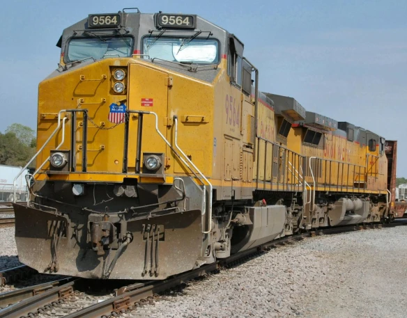
Regular snow plows work by forcing the show aside and for the majority of areas this is just fine.  In winter months you can often see plows fitted to regular locomotives as with UP 9564 in the photo below. (Picture from Home Town by Handlebar).

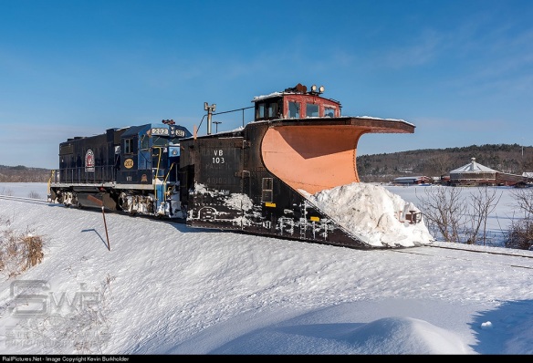
But when it gets a bit deeper the plow has nowhere to push the snow so it needs to be lifted above.  This can be done with a larger dedicated plow which is pushed by locomotives as shown below. (Photo by Kevin Burkholder and displayed on Railpictures).

The large ‘scoop’ at the front pushes the snow up and out to the sides, the ‘wings’ (behind the plow with VB 103 marked on the side) can be adjusted to push the snow even further, and retracted to pass objects close to rails.  Plows like this come in all sorts of shapes and sizes as railroads tended to build their own out of freight cars, caboose and tenders.  The important thing is they needed to be heavy as hitting a snow bank at speed creates quite an impact as you can see in the video below. (courtesy of James Adeney from You Tube).

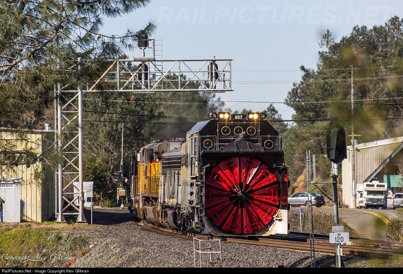
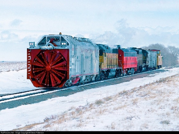
But when the snow gets really deep you simply can’t push through so out come the rotarys.  At the front, as shown below, is a large rotating cutting face or fan.  This breaks the snow down and forces it out a chute on the top.  The chute can be angled to the left or right and throws the snow far away from the railroad. (Photo by Alix Gillman and displayed on Railpictures).

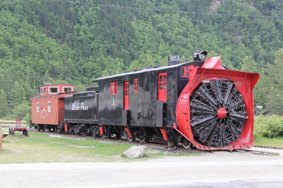
The rotarys move much slower than the plows as they cut through but the only limitation is the amount of power to the fan and how much tractive effort is pushing it into the snow.  Typically rotarys are not self-propelled, all the power they generate is used to drive the fan, so they will often be seen with several power units pushing from behind.  The early rotarys were all steam-powered which gave the added advantage of heat.  Not only would the boiler provide steam to drive the fan but also to melt the ice which built up around the front.  The steam rotary below, pictured by Brian Snelson on Flicker, was built in 1898 and was used right up until 1968.  It’s typical of an early design with a  traditional steam engine tender behind for fuel and water.

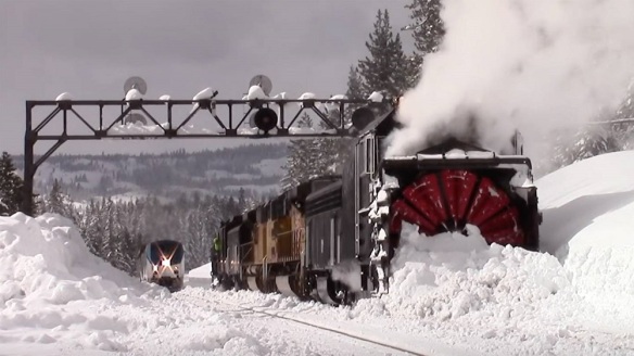
As these machines were not in constant use, often only used every five to ten years, they were kept in running order but had little need for updating.  However as steam started to become obsolete on the class one railroads they started converting them to diesel and electric power.  A good example of this is the Southern Pacific with their route over Donner Pass.  They converted the actual rotary to electric power.  It was also coupled to a spare EMD F7 B unit which had its traction motors removed and all four installed into the rotary to power the fan.  The B unit produced the power for the fan motors.  A steam generator was also fitted to keep the front clear of ice and supply warmth to the crew.  Controls were added so the crew could control the pushing locomotives from up front.  In the image below you can see two rotarys and their F7B units, one at each end of some modern locomotives, as they wait for a passenger train to pass.  Up in the high mountains of Donner Pass they often worked like this so they could clear snow in both directions continuously. (Photo by Jake Miille Photography)

This photo is accompanied by a short video of the rotarys working on Donner Pass on February 25th, 2017.

Although the Union Pacific Railroad had many steam rotarys over the years purchased from specialist manufacturers, in the late 1950’s and 1960’s they also built some of their own and it’s one of these which I’m creating a model of.  As they started from scratch on their new rotarys it was easy to build them just how they wanted.

UP 900080 was constructed in 1958 at the UP Omaha shops.  It was built on the frame and rear truck from a retired ex C&O steam tender.  It has a 1750hp diesel engine to drive the 12′ rotary fan, weighs 347,240 pounds, is 50′-9″ long and 16′-8″ high. (Photo by Steve Patterson and displayed on Railpictures).

UP 900081 was constructed in 1966 at the UP Omaha shops again on the frame and rear truck from a retired ex C&O steam tender.  This time UP put in a 3000 hp diesel engine making this rotary the most powerful and weighing 367,400 pounds also the heaviest rotary in the United States.  It is 52′-2″ long, 17′ high and the rotary fan is 12′ in diameter.  (Photo by Joe Bracey and displayed on Railpictures).

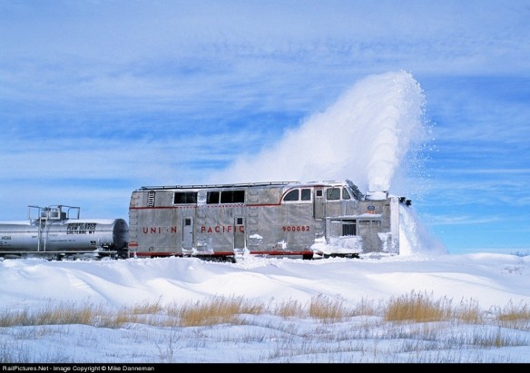
UP 900082 was constructed in 1971 also at the UP Omaha shops. It has a 2500 hp diesel engine, weighs 284,500 pounds, is 55′-3″ length, 17′ high and has a rotary fan 12′ in diameter.  (Photo by Mike Danneman and displayed on Railpictures).

Out of the three 900080 and 900082 are still in service but sadly 900081 was damaged in 1994.  UP retired the rotary but donated it to the Museum of Transportation, St. Louis, Missouri later that year where it’s now on display.

As 900081 was the most powerful, 900082 currently holds that honor, it’s this one which I’m modeling, although it’s very similar to 900082 so it could be used for either.  The plan is to have a free rolling chassis but still have a motor inside to power the fan.  To do this I will most likely use a commercial chassis from a diesel locomotive and remove the drive gear from the truck towers.  Then I’ll connect the drive shaft to the fan.  Sounds very similar to what SP did with theirs!

Next week I’ll share with you some of the design drawings and go over some of the finer details I intend for the model.  To round-up this week’s post I’ll leave you with two videos of the White Pass & Yukon Railway’s steam rotary plow doing what it does best. (Both courtesy of Murray Lundberg from You Tube).

Adding Real Coal Loads To Hoppers

Happy New Year!

2018 is here and after a little time off over the Christmas holiday I’m ready to get stuck back into modeling, 3D printing and generally anything train-related.  And what better way than a blog post about something I’ve been working on that you can also do.

Over the years I’ve collected many different coal cars and the only thing I don’t like about them is the identical plastic coal loads.  So this week’s post is a ‘how to’ for adding real coal loads to hopper cars.

Of course modern block coal trains do have very similar loads in the cars because they are all filled from the same place at controlled intervals and look something like this. (Photo taken by Lewis Bogaty, see his blog here)

But depending on where the load comes from will depend on the size of coal pieces as shown in the image below. (Photo from Virginia Tech Imagebase).

The shape of the load is also effected by the type of coal chute and the operator.  For me I like my coal loads to look something like the cars below; with a twin mound and a random unevenness.  These are Lionel O scale cars, and if you look closely you can see the coal loads are identical!

So what do I do?  Firstly I pick a coal to use; I’ve been using Woodland Scenics’ Mine Run coal, it’s not actually coal but looks just like it and it weighs next to nothing.

Unless the car has a load which is the right shape and set low in the car (I’ll explain what to do with those later) I remove the original load.

This would also be the best time to add any weathering to the car so it doesn’t get onto the coal load. But for this particular car I haven’t done that as it already has a grubby look.

Next I cut a piece of rectangular card which is the same size as the top the car.  It doesn’t have to be an exact fit but it wants to be snug.

The card wants to be set down from the top rim.  This has two functions, it gives me a level to work from and saves me filling the whole car with coal.

To hold it in place I use a splash of super glue on each end.  Any glue will do but I like to do this fairly quickly and superglue sets very fast.  In my previous posts you may have seen me use the Gel superglue which I normally prefer as it doesn’t run.  But today I want it to run into the gap so I’m using the regular stuff.

Next I cut a second strip of card which is thinner than the original, about half as wide.

The second strip is then cut into two pieces.  These will form the mounds, and if you want three mounds simply make them shorter and add a third.

Using my craft knife I cut the mounds at forty-five degrees to make a chamfer.

I repeat this on all four sides.  It doesn’t have to be perfect as it’s going to be covered with coal!

I then put some super glue where the mounds will be.

And place the mounds, trying to get them centered in the car.

Next I use a white glue, simply placed in the car as below.  Woodland Scenics’ Scenic Cement will work or any white glue but I like to use Tacky Glue, simply because it sets quickly and speeds up the operation.

Using and old brush I spread it all over the card trying not to get any on the top edge of the car.

Then the fun bit, simply pour the coal on top.  I recommend doing this on a piece of paper so the excess coal can be picked up and reused.

After about 5 minutes, if you are using Tacky Glue, turn the car over and all the excess coal will fall off.

Pick off any bits that have stuck to the top edge before they set permanently.

If, like me, you want the mounds to be a bit higher simply add a bit  more glue to the top of the mounds.  Also if there’s a hole or gap add some glue there as well.

Then re-cover the car with coal.

After another 5 minutes tip over again to remove the excess and you should be left with a natural-looking load of coal.

I then leave the car overnight just to make sure all the glue sets.  And the car is now ready for the railroad.

Earlier in the post I spoke about cars which have a plastic load which is the right shape and set low in the car.  When the load is set low there is room on top for extra coal without it looking over full. These are easy to do, simply cover the plastic load with white glue, again avoiding the top edge, and pour on the coal.  Even though the plastic loads will be the same shape the poured on coal will take a slightly different pattern each time.

And that’s it for the first post of 2018, I will be back next week with more. In the meantime I’d just like to wish you a great New Year and I look forward to sharing more of my train projects with you.