On the weekend I was at the National Model Railroad Association (British Region)’s winter meet and model railroad exhibition in Benson, Oxfordshire, UK and I wanted to share some of the layouts with you.
This is the first exhibition on the calendar for the NMRA (BR) and it was also my first visit. The show is a one day show only, but after talking to several of the regulars it appears to be a very popular show and this year was no exception despite the bad weather and flooding we have been having over the last week.
I wasn’t just visiting the exhibition, I was there with my club, the Gosport American Model Railroad Group, and we had brought part of our modular layout, Solent Summit, along for the day. So, in between running trains and chatting to the public, I had some time to look around a few of the other layouts and stalls.

The hall in Benson was a nice size and was filled with layouts and stalls and although there was also more upstairs I didn’t make it that far as I had trains to run!
Here are some of the layouts that were at the exhibition;

This is a beautifully detailed HO layout based in Maine, USA in a fictitious setting.

Everywhere you look there is fantastic detail and even though I have seen it before I keep spotting new things such as the crab nets on the dock.

The layout consists of a small station and yard with a train ferry entrance.

For me, the best parts of this layout are the buildings and scenery.


In particular I loved the lighthouse and the detailing of the action around it around it.


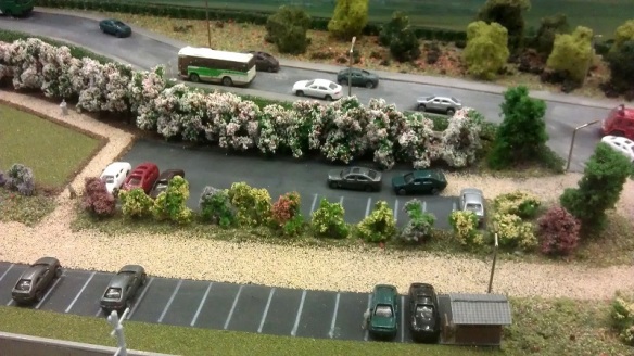
This is a Z sale layout by Peter McConnell. The layout is a city scene set in Japan with an electrified two-track main line running round to a storage yard at the rear. In the front there’s a station and yard scene. A branch line runs out from the station to the yard which is not electrified.

The station has three platforms, the nearest two being an island platform on the main line.

Leaving the station the main line and branch run parallel around to the yard.

I’ve never worked in Z scale so I am often impressed by the level of detail, as I was with this one. The trains ran very smoothly and at a good scale speed.
Black Diamonds
This N scale layout is a modular layout that can be assembled in a variety of ways, from my understanding this was only a small part of the overall layout. All the modules here have been laid with Atlas code 55 track. The layout is in a dog bone configuration with a double track main line and a yard at each end. The layout is setup for running long trains through large open spaces.


Dave Dawes’s Dawes Creek is an N scale layout set in Australia. It has a beautifully modeled station scene with a small yard. Both ends of the main line run around to the rear where there is a staging yard.


For me the highlight of this layout were the locomotives an rolling stock, in particular loco no. B64 which has the look of an double ended American F unit. All the locomotive shells are resin casts by Aust-N-Rail and they are fitted onto American prototype chassis.


Dave has more about his layout on his website www.dawdawes.com.
Kathy Millatt
Kathy is the Atlantic director of the NMRA and she had brought along part of her modular On3 (O scale narrow gauge 3 foot) layout to do scenery demonstrations throughout the day.

I was particularly impressed with the track work on the dual gauge section: this was all hand built.


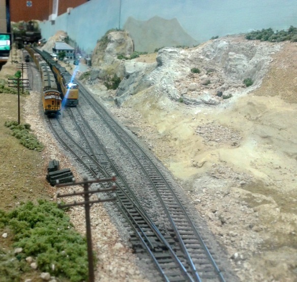
N scale in Switzerland
This great little N scale layout, which I forgot to get the name of, is set in the Swiss mountains covered in snow. There are three loops running around the layout and a scene on the high line of a train wreck due to an avalanche.


Solent Summit
So at last we come to the layout my club brought. Solent Summit is an N scale modular layout based on a oNe track system; this means all the modules conform to the same set of standards such as the main line must be 4″ from the front. Therefore the modules all work together in a variety of configurations. At this meet in Benson we brought fourteen modules, which is about a third of the modules we currently have finished. The overall layout took the form of an oval and we will pick it up in the yard;

This yard has six through lines exiting onto a single main line around the bend.

After rounding the bend the line approaches tunnel 41.


Emerging from tunnel 41 the line rounds the bend next to Ted’s Farm.


After passing Ted’s farm the line enters Solent Summit. Here the main line carries on through the middle, with a station line on the inside and a passing line on the outside.
In the middle of Solent Summit there is a second, shorter passing loop.


Leaving Solent Summit, the line returns to a single main line and runs past the coal mine.


The coal mine has three lines, the near side track is the main line which runs through a tunnel.


Emerging from the tunnel the line crosses Hells Glen on a steel trestle and enters another tunnel.


Emerging from the second tunnel the line passes the power station where the main line is again the near side track. The two lines going into the power station are also the first two lines going into the coal mine. They run behind Hells Glen out of sight.

 Leaving the power station the line rounds the bend and returns to the yard.

So that’s a taster of the Benson NMRA (BR) winter meet. There’s a lot to see at this show, and plenty of stalls, so it’s definitely one for my calendar next year, and I hope to see some more new faces there.


You must be logged in to post a comment.