Converting An N Scale Bachmann F7 to DCC

The N Scale Bachmann F7 has had three revisions to date and the most recent one, made available in 2013, is supplied with DCC.  But what about the first two?  In this post I will show you how I add DCC to the locomotives in a cost-effective way.

The Bachamm F7 over all is not a bad locomotive; it has great polling power and the body work, although not as good as the Intermountain model, is nice.  They do tend to run a bit noisily so installing a sound decoder for me was not an option. As I have several of these, installing a basic decoder in each starts to add up, so again I am going to use one decoder to power two locomotives.  When doing this it is important that the locomotives run at similar speeds when used together on DC power.  Luckily these do, but if yours don’t I have already covered a topic like this and you can read about it here.

Bacmann F7 DCC Install 34

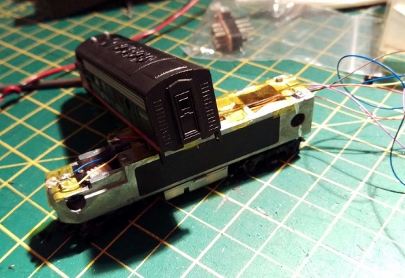
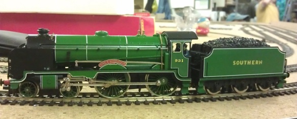
The F7 A & B set I am converting to DCC, as shown above, is the second version but both first ‘Plus’ version and the second ‘Spectrum’ version are very similar in chassis shape and design so this method will work for both.  You can read about the difference in Spookshows N Scale encyclopedia here.

With the shells removed, as you can see below, both the A and B units are exactly the same with the exception of the A unit having a light bulb pushed into the hole at the front.  To remove the shells simply spread them at the fuel tank and they will un clip then lift off.  You will also see that the chassis totally fills the A unit shell leaving no room for a DCC decoder to be installed.  But because the B unit has the same chassis there is space in the B unit where the cab would have been so I will be putting my decoder there.

Bacmann F7 DCC Install 1

There are no wires inside the chassis, which is split into two, and the light bulb simply picks up power by touching the chassis halves.  A down side to this when running on DC is the light comes on in reverse as well.  And for DCC,  the motor picks up its power in the same way so we will need to isolate it.

To take the chassis apart is fairly simple.  First remove the fuel tank by undoing the screw in the middle.

Bacmann F7 DCC Install 2

Then undo the two chassis screws in the left half and it will lift off.

Bacmann F7 DCC Install 3

Turning the left half over you will see a spring projecting out of the chassis.  This is the bottom motor contact that connects the left half to the motor.  This spring needs to be removed simply by pulling it out.

Bacmann F7 DCC Install 4

With the two halves separated the whole assembly will come apart.  The motor simply lifts out and the truck assemblies will already be free.

Bacmann F7 DCC Install 5

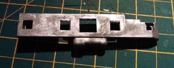
The right half of the chassis has a stub that sticks out and connects to the top motor contact.

Bacmann F7 DCC Install 37

This stub needs to be removed.  This can done with a good pair of large side snips and a file.  The chassis is made from a fairly soft metal so it files down quickly.  In the photo above you will also see the inside of the black tape that has been put across the holes in the chassis. I believe Bachamnn added this to the second version to prevent particles getting into the motor winding.  Also as it is sticky on the inside it will catch any particles thrown off the motor brushes.  You can see some of those just below the stub. Filling the stub will create metal fillings which you also don’t want to get in your motor so once the stub has gone remove the black tape and clean the chassis half to remove all the filings.  A stiff brush will normaly do this.

With the chassis half clean, you can do a test fit with the motor to make sure the motor contacts to not touch the chassis.

Bacmann F7 DCC Install 6

To do a proper test the chassis can be resembled with just the motor in it and you can do a continuity test with a volt meter.  Dont forget to put the little plastic spacers back in, there is one for each screw and one in the fuel tank.

Bacmann F7 DCC Install 7

Next we need to create a path for the bottom motor wire.  As there is no room inside, the wire will have to come up the outside of the chassis but as the shell is a snug fit around the motor, there is still no room.

Bacmann F7 DCC Install 8

So in order to make room I have filled a V grove up the side of the right chassis half.

Bacmann F7 DCC Install 9

The grove also continues round under the fuel tank.  The grove needs to be just big enough to take the wire you are using so the face of the chassis and wire will be flush.

Bacmann F7 DCC Install 10

Once any metal fillings have been removed the chassis is now ready and we can turn our attention to the motor.  The motor body is already isolated from the contacts so all we need to do is add our wires to the contacts.  Although we can change this later it is useful to add the right wires onto the motor now so we know which is the positive side.  Normally orange is the positive motor wire and gray is the negative.  But there is no indication on the motor as to which is which.  On my work bench I have a DC controller with a test track and a pair of wires.  When a train is running forwards and to the left the right rail is my positive, colored red, and the left is my negative, colored back.  Touching the red and black wires onto the contacts will make the motor spin and in the configuration shown below you want the motor to spin anticlockwise.  That would be the same as forwards to the left.

Bacmann F7 DCC Install 11

To add the wires I quickly heat the contacts with the soldering iron, for one to two seconds, then add a little bit of solder just to tin the contact. You don’t want to over heat the contact is it is a perfect conductor of heat and there are plastic parts inside. Next I tin the end of my wire, hold it to the contact and quickly touch it with the iron.  The two tinned areas fuse and you have a good connection.  Note the wires need to be long enough to run up inside the locomotive and across to the B unit.

Bacmann F7 DCC Install 12

Before re-assembling the chassis I also change the couplings on the loco.   When these where being run under DC I used Unimate couplings from Red Caboose.  These provide a nice close couple that will not come undone on the track however as I will now have wires running between my locos I don’t want them to come uncoupled at all.  To do this I will replace the Unimates between the A and B unit with one of my fixed link couplings.

In the image below you can see the underside of the Bachamnn power truck.  Just to the right of the tuck and before the coupling box are a pair of pins that can be squeezed together with a pair of needle nose tweezers.  This will cause the coupler box to pop off.

Bacmann F7 DCC Install 13

Inside the coupler box is a spring that fixes over the peg on the back of the coupler.

Bacmann F7 DCC Install 14

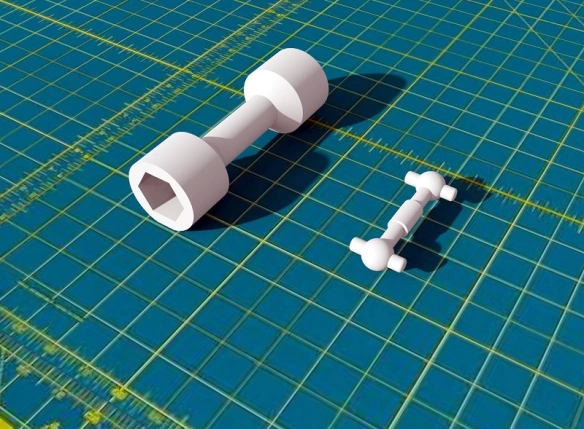
My 3D printed fixed coupler is a direct replacement for the old Rapido style couplers so drops right into the Bachmann coupler box.

Bacmann F7 DCC Install 15

For now I only fixed one truck to the fixed link but you could do two, one from the A unit and one from the B unit, at this point.

Bacmann F7 DCC Install 16

Now the chassis can be reassembled.  Note the wire form the bottom motor contact is coming out the bottom of the chassis in front of the plastic spacer. (I know the wire is brown and not gray but I have run out of gray!).  Also when you refit the tracks make sure the metal contact for power pickup is rubbing against the underside of the chassis not the inside as this will prevent the trucks from rotating.

Bacmann F7 DCC Install 17

The brown wire (bottom motor connection) can now be placed in V grove that was filed earlier and the fuel tank can be replaced.  Also I have put some Kapton Tape over the holes in the chassis to replace the black tape I removed, this also holds the wire in place.

Bacmann F7 DCC Install 18

Now the motor is isolated and wired up the next two wires are the power supply.  On top of the chassis are four nubs that the shell sits onto.  Interstingly these are slightly narrower on the bottom than they are on the top so all I do is wrap the end if my wire around the base of the nub a full 180° and solder it in place.  I have yet to have one of these fail.  And as long as there is nothing sticking up above the top of the nub the shell will still fit.  The red wire goes to the right side and the black, or purple in my case, goes to the left.  I must order some more different colored wire!

Bacmann F7 DCC Install 23

The last wires, for the A unit, are for the light.  The standard light is a light bulb and these can be power-hungry and get hot.  So I replace mine with warm white LEDs. Below is a comparison with standard 3mm LED on the right and a 1.8mm LED on the left which I will be using.

Bacmann F7 DCC Install 19

As all LEDs need a resistor in line I make the resistor a part of the headlight by folding one of the resistor legs back onto its self and soldering it to the LED.

Bacmann F7 DCC Install 20

Then I wrap it all in Kapton Tape to prevent it shorting.

Bacmann F7 DCC Install 21

Finally I trim back the legs ready to solder on the wires.

Bacmann F7 DCC Install 22

The LED will sit in the same place as the light bulb.  To protect against shorts I put a strip of Kapton Tape over the nose then cut out the hole with a sharp knife.

Bacmann F7 DCC Install 24

The LED light assembly then pushes into the hole and the legs, sitting on top of the Kapton Tape, can be soldered too.  As LEDs only work in one direction it is important to know which is the positive and negative.  The blue wire, matching the decoder, is the positive.

Bacmann F7 DCC Install 25

With all the wires in place they can now be taped down with Kapton Tape so they are tidy and clear of the shell.  Check to make sure the trucks rotate freely.

Bacmann F7 DCC Install 26

To fit the shell I you could simply run the wires through the window in the connecting door at the back but this can be really tricky so using a sharp knife I simply remove the plastic under the window.

Bacmann F7 DCC Install 27

This allows the shell to be lowered onto the chassis without pulling or pushing on the wires.

Bacmann F7 DCC Install 28

When it comes to the B unit I do exactly the same, except the wires run to the front and there is no light.

Bacmann F7 DCC Install 29

To join all the wires up I like to uses little bits of cooper strip board.

Bacmann F7 DCC Install 30

These are then superglued to the nose of the B unit.  You could use one piece and glue it to both sides of the chassis but this would mean the unit could not be taken apart for repair if needed.  You also need to make sure the DCC decoder will fit behind the cooper strip boards and they do not protrude out side of the chassis so the shell will still fit.

Bacmann F7 DCC Install 31

Once you are happy with the placement of the cooper strip board, solder the wires together, orange to orange etc. The red and purple (black) can go directly onto the B unit chassis.  At this stage there are a few checks that you should make.  First, using a volt meter set to a continuity check, check that the left B unit chassis is connected to the left A Unit chassis, and repeat for the right.  Secondly check that the left and right chassis are not connected to each other.  Thirdly check that none of the chassis are connected to any of the cooper strip board terminals.  Then using 12v DC wires from a controller test that both motors are running the same direction when you connect them to the orange and brown (gray) wires and finally test the headlight works when you connect the 12v DC wires to the blue and white wires.

Bacmann F7 DCC Install 32

I also connected the fixed link coupler to the front truck of the B unit at this stage.

The last stage is to solder the six decoder wires to the copper strip board terminals and chassis points.  I have used a Digitrax DN163, it was a bit of a tight fit because this decoder has a plug on it making it thicker than normal but most N or Z scale decoders will fit.

Bacmann F7 DCC Install 33

I cut the front door of the B unit shell to fit over the wires the same as I did with the A unit and fitted it onto the chassis.  And there you go; two powered locomotives connected with a draw bar, which is prototypical, and one decoder.

Bacmann F7 DCC Install 35

But there is one more thing that you can do to make this even better and that is to have four locomotives with two decoders.

Bacmann F7 DCC Install 36 Normally the locomotives would all have different numbers but to make things easy I have configured the two DCC decoders to be both the same address and switched the rear pair to run in reverse as their forward direction.  This means you don’t have to consist the locomotives, and they won’t take up two slots in your DCC command station. This can all be done by changing the configuration variables or CV values; which can be fairly in-depth subject so it is something I will cover in a later post.

Re-powering A Dapol Semaphore Signal

Recently I have been working on a British outline OO layout which had some working semaphore signals.  Sadly some of these signals had suffered some electrical damage which rendered their control circuit boards inoperative. In this post I will be sharing with you a few simple methods of repairing Dapol semaphore signals.

The Dapol semaphores, as shown below, are nice looking signals and have a fairly basic drive system which is self contained in the tube below the signal.  Above ground there is a nicely detailed rectangular post with the rotating arm on top.  The arm is connected via a crank to a push-rod that runs down behind the post.  You will be able to see this in some later photos.  The glass lenses in the end of the arm are transparent and a small LED shines through creating the correct color.

Dapol Signals 1

Below ground is where all the clever parts are.  Interestingly the drive system on these OO signals is also used for their N Scale signals; Dapol have simply changed the size of the signal on top.  In the large threaded tube at the bottom of the signal is a circuit board, electric motor, gear rack and worm gear.  After the large nut has been removed there is a tiny screw at the base of the signal which holds the two halves of the tube together.  Once that has been removed the tube can be separated.

Dapol Signals 2

The motor is in the left half and the circuit board is in the right.  You can also see the push-rod that runs up behind the signal pole in front of the ladder.  And if we zoom in you can see below the push-rod is a spring.  This spring is attached to the push-rod and when it’s moved up and down the signal arm moves up and down.

Dapol Signals 14

The two pairs of metal contacts are part of the circuit board; as the motor spins the worm gear it drives the rack either up or down pushing the rod.  A spigot sticking out of the rack touches one of the pairs of contacts creating a circuit and telling the circuit board that the rack is at the end of its travel.  However as the circuit board is damaged these are of no concern to us.

As new, the signals work by providing 16v AC power to the red and black wires.  This powers the circuit board and the LED at the top of the signal pole.  Then by simply touching the two yellow wires together, using a momentary Push-To-Make switch, the signal will change. Even when you let go of the switch the motor will keep going untill the rack gets to the end of its travel.

On the first of the two damaged signals only the motor drive function was inoperable, the light still worked when 16v AC power was applied, so the circuit board was still producing low voltage DC which is also needed to drive the motor.  In the picture below you can see the wire connections.  The red and blue are the DC feed to the motor.  The tiny red and, hard to see just above the yellow, tiny black are the LED feed that run up inside the signal pole.  The big red and black are the 16v AC power in and the yellows are the activators.

Dapol Signals 4

So to fix this signal I removed the motor wires from the circuit board and extended them by soldering on some more wire and heat shrinking the joint.

Dapol Signals 5

Then I removed the yellow activator wires from the circuit board and added a pair of wires to the LED feed connection points.

Dapol Signals 6

The signal was then reassembled with the new wires coming out of the bottom.

The next step was to take the low voltage DC power, coming from the new blue and green wires, out to the layout control panel. Then, using a momentary double pole double throw (DPDT) switch, return the power to the motor wires, in positive or negative, to make the motor go one way or the other. The DPDT switches I use are toggle switches as shown below.

Dapol Signals 16

These have six connections on the bottom.  When it is thrown one way it joins the middle pair to the top pair and the other way joins the middle pair to the bottom pair.

So, if the incoming low voltage DC power is connected to the bottom pair, then reversed and connected to the top pair, throwing the switch one way or the other will reverse the DC power.

Dapol Signals 15

The motor is then connected to the middle pair of terminals, not shown above, and the signal can be manually controlled. My apologies as I got a bit carried away with the work and so didn’t take any more photos of this particular signal.  As the switch is a momentary, when you let go it springs back to the middle and stops the motor.  There’s no danger of pushing the motor too far as when the rack gets to the end of its travel it simply stops, although the motor keeps spinning.  The spring on the end of the push-rod, and there is another one on the bottom of the rack, supply just enough pressure to make the rack re-engage with the worm gear when you want it to run the other way.

This fix, although functional, is not ideal as you are still relying on a damaged circuit board and all the small parts inside the tube.  Plus you have to hold the switch untill the signal has reached its position.

The second fix I have for these signals is a bit moire drastic but I think in the long run is a more durable solution.

The second signal’s motor and circuit board had failed so I removed all of the parts from inside the tube.  Sadly the LED had also blown on this particular signal so the wires for that will go as well.

Dapol Signals 7

As all the points on this layout are powered with Seep point motors it made sense to power the signal in the same way.  Seep make a special point motor with a latching spring which is designed to work with hand-built points that don’t have a latching spring of their own.  The latching spring means the motor will stay in the required position even though the spring on the push-rod will be pushing back.  This latching point motor was mounted to a ‘Tee’ shaped mount as shown below.

Dapol Signals 8

There is a slot for the motor throw bar to pass through and the large hole above the throw bar is for the signal tube.

Dapol Signals 9

You can see the latching spring under the motor cross-bar.

Dapol Signals 11

As the tube on the bottom of the signal was now empty it could be reduced in length; this was also necessary so it didn’t hit the throw bar.  The last thing to do was to connect the throw bar to the signal push-rod.  However there is a problem in that the point motor movement is more than the signal needs, and as the point motors are powered by Capacitor Discharge Units the motor bangs over very hard which will damage the signal.

To counteract this I made a very basic omega ring out of thin nickel rod.  One end was superglued into the spring on the bottom of the push-rod, the other was looped around the motor throw bar.

Dapol Signals 13

Although basic, this omega ring absorbs the sudden shock from the point motor as well as any extra movement while still supplying enough force to move the push-rod.  The two shorter tube halves were glued together and the ‘Tee’ mount was screwed to the underside of the layout.  The signal was then put though the hole in the layout and mount.  Before the large nut was tightened up the signal could be tilted to one side to alow the omega ring end to be slid over the point motor throw bar. Once tightened up the omega ring could not slide off the throw bar, but as an extra measure I glued a small washer onto the end of the rod.

This second fix was a lot better because the signal changed quickly with a single touch of the switch and any wiring is the same as a standard point motor.

These signals have also been modified in a similar way with servo motors which gave a very nice smooth action and this might be something I will try next time.  If I do I will share it with you.

A Replacement Drive Shaft for an N Scale Bachmann 4-4-0

Since releasing my N Scale MDC/Roundhouse/Athearn 2-8-0 & 2-6-0 drive shaft repair kits back in 2014, which can be found here, I have been asked to produce replacement drive shafts for several other N Scale locos.  One of these is the Bachmann 4-4-0.  So in this post I will share with you the results.

The Bachmann 4-4-0 or ‘American’ has been around since 1979 and for years was the only choice for a ready-to-run model of this locomotive.  The first generation, as pictured below, housed the motor in the tender.  This was then connected via a thick drive shaft to the driving wheels through to the back of the cab.

Bachmann 4-4-0 Old Style

The model had several improvements over the years but the one that I’m interested in  was made in 1998 when the drive shaft was changed, leaving the locomotive looking like the one below.

Bachmann 4-4-0 New Style

Together you can see the locomotives are basically the same, the newer one just has finer paint and details.

Bachmann 4-4-0 New & Old Style

The original locomotive’s drive shaft was a Hex-Cup style, pictured on the left in the image below.  This drive shaft was fairly bulky and dominated a lot of the space between the cab and tender.  On the end of the motor and worm gear inside the locomotive is a hexagonal nut that the ends of the drive shafts fit over.  This arrangement allows the linkage to flex as it goes round curves in the track.  The improvement in 1998 was to replace the bulky Hex-Cup with a Ball-Cup and peg design, as shown on the right.  The ball fits into a cup with slots on ether side.  The ball can rotate in all directions within the cup and the pegs rotate the shaft via the slots.

Bachmann 4-4-0 Drive Shafts

The Ball-Cup and peg design, apart from being much smaller, makes for a smoother motion which improves the performance of the loco.

However, as with all small parts it’s possible to lose these bits when servicing the loco or possibly they could break, particularly with those tiny pegs on the ball and cup connection.

Bachmann do sell replacements parts for the newer style drive shafts but they have been out of stock for a long time. As for the older Hex-Cup shaft it is likely that these are no longer available.

So I have drawn up both drive shafts and made them available on Shapeways.

Bachmann 4-4-0 Drive Shafts Rendering

The larger and earlier Hex-Cup type is available here and can be printed in either Shapeways’ Frosted Ultra Detail or their Frosted Extreme Detail materials.  As usual with these materials they can be used directly out of the bag but they are a white or translucent color.  They can be painted but they will need of be cleaned with a product such as Goo Gone in order to remove any wax residue left over from the print process.  The wax will prevent the paint from drying or adhering to the part.

The smaller Ball-Cup style drive shaft is available here and comes in a pair.  This is because, unlike its predecessor, the Ball-Cup drive shaft is a bit more delicate, particularly around the pegs so just in case the first one gets broken I have supplied a spare.  Again the second generation drive shaft is printable in both FUD and FXD materials from Shapeways.

This Ball-Cup and peg system has become a commonly used drive shaft across a lot of model manufactures but sadly the actual drive shafts are all a bit different; whether it is length or peg diameter the chances of one manufactures drive shaft fitting into an others locomotive is slim.  However if you are in need of a drive shaft for a particular model please let me know through the contacts page and I can draw up the parts and make them available on Shapeways.

Happy New Year and a Look Back at 2015

Happy New Year!

For this week’s post, being the first post in 2016 and because I did it last year, I thought I would take a look back over the 3D printed and metal products, how-tos and exhibitions from 2015.

January saw the release of my O scale Union Pacific excursion train tenders.  These had already been released in N Scale and HO but to scale up to O was an interesting challenge.  Both Joe Jordan and Jim Adams were made available and they can be found here.

O Scale Tender Shells Finished 6

These were a lot of fun to work on after all the N Scale models and they looked fantastic.  Only the bodies and detail parts were 3D printed as they ran on Lionel trucks and chassis.  The Lionel parts have plenty of weight, which is very important with O Scale.

The other new release for January was my N Scale dummy chassis for Atlas’ Alco C-628 & C-630 body shells.

Alco C-628 Dummy Chassis Render 3

This chassis was also made available with the option to fit the original circuit board for lighting using a circuit board clip as shown below.

Alco C-628 Dummy Chassis Render 6

This chassis is ideal if you have purchased one of my Baldwin DT6-6-2000 or RT-624 kits and have a spare shell left over from the donor locomotive.  In the line up below only the middle locomotive has a powered chassis, the other two are dummies using my chassis kit.  The kit can be found here.

Alco C-628 Trio - x2 Dummys

In February I released my replacement gears for Rivarossi F9 O Scale locomotives.

Rivarossi F9 Scale Gears Button

These replace the original drive gears on the axles that have a tendency to split.  Below you can see a set that has been fitted to the loco.

Rivarossi F9 (O Scale Gears 6 (Mike Dobson)

The Rivarossi F9 chassis is popular with O Scale modelers and here it is under a GP7 body shell on Mike Dobson’s home layout.  The incline is fairly steep so it’s a good testament to the strength of the gears.  They can be found here.

February also saw the start of my C-855 project which you will be seeing more of very soon.

Alco C-855 WIP Render 5

March brought detail parts such as my replacement N Scale horns and these came in a variety of styles.

Horns Type 3-3 Horns Type 3-2 Horns Type 3-1

These are now available here in several configurations and there will be more coming this year.

April introduced my N Scale Etched Chain Link Fencing.  The fencing is made from stainless steel sheet and is currently available in three configurations which can be found here.

Chin Link Fence Blog Post 36 Chin Link Fence Button Chin Link Fence Blog Post 4 Chin Link Fence Type 1 Chin Link Fence Type 3

Because of the new fencing and other metal products becoming available I created an Etched Metal Additions page in the shop.

Shapeways also announced their new higher quality 3D printed material FXD.

Shapeways-fxd-email-hero-625x468

This new material has a 16 micron layer thickness which is sharper and finer than the FUD which has a 29 micron thickness.  The FUD is still a fantastic material so, as the FXD is more expensive, I now offer my models, where appropriate, in both materials.

May brought more detail parts such as the replacement eccentric rods for MRC/Rowa N Scale 2-8-4 locomotives.

Berkshire Eccentric Rod Repair 1

These are designed to simply clip in as a direct replacement, as you can see below.

Berkshire Eccentric Rod Repair 3

June introduced some more N Scale replacement horns and I started sharing my work on my modular layout sections, beginning with my 3D printed trestle bridge deck.

WS&F Trestle Parts 5 WS&F Trestle Parts 6 WS&F Trestle Parts 9 
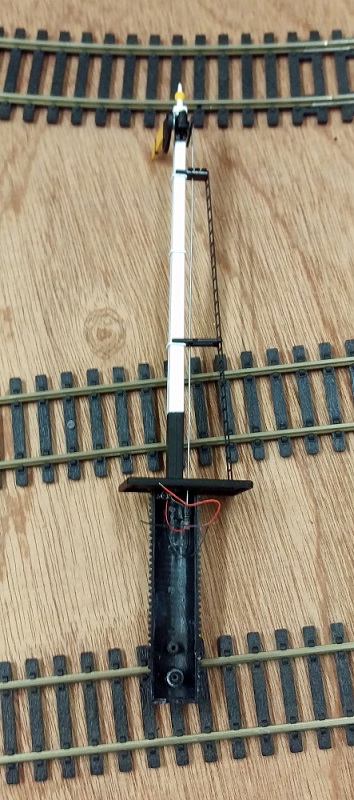
You can read more about the trestle parts in part 1 here and part 2 here.

The C-855 project also took a step forward with its metal chassis extension parts.

C-855 Chassis Extenders 1

C-855 Chassis Extenders 9

C-855 Chassis Build 15

You can read more about the chassis extension here and here.

With the summer getting underway, July was a quiet month for new releases, with only a set of etched brass name plates being released for a OO gauge Schools class 4-4-0 locomotive.

New Name Plate New Name Plate 3 New Name Plate 2

The rest of the month was mostly taken up with working on my modular layout getting ready for exhibiting, and I did a how-to on casting your own rocks, which you can read about here.

Rock Moulding From Bark 9

In August I gave some demonstrations including how to create cheap but effect Nut, Bolt & Washer details for trestle bents which you can find here.

NBW Blog Post 16

You can find my how-to on using your rocks to build river & railroad canyons here.

Warsash Canyon Creation 16

And how to paint your rocks which you can find here.

Colouring Rocks 12

And to close out August I released my brass Addition kits for my P42 mirrors and GP7/9 detail parts.

JTP Additions P42 Mirrors

JTP Additions GP7-9

They can both be found in the etched metal Additions page here.

September brought some more replacement parts and this time it was a crank pin for a Minitrix 4-6-2 Britannia.  You can find the part here.

Minitrix Crank Pin 5

Minitrix Crank Pin 8

Minitrix Crank Pin 9

I also did two more demonstrations; one on how to ballast track which you can find here.

BalistingTrack 13

And one on how to make your own Talus and rock fall for river beds which you can find here.

Making Talus 18

November was mostly taken up with exhibition reviews (see towards the end of the post) but I did share with you my new design for 3D printed speaker enclosures which you can read about here.

Speaker Enclosure Prts Raw.

These will be available shortly but for now you can see some examples of the working prototype here.

Speaker Enclosure Base plus 2

December is normally a short month for me and I shared with you a how-to on adding resistors to N Scale wheelsets for track detection.

Wheel Set Resistor 12

As well as all the new products and how-tos I also visited a few exhibitions and a home layout and you can find them all below.

Poole & District Model Railway Society’s Exhibition 2015, November 8th

NMRA (BR) Annual Convention 2015 – 23rd to 25th October

Southampton Model Railway Exhibition 2015, January 24th & 25th

David Townend’s Mckinley Railway

And that rounds up 2015, it’s been a good year and I’d like to thank you for your continued support. Here’s to a happy and finely modeled 2016!