Over the Christmas period I have not done a great deal of modeling or drawing; the projects you’re waiting to see finished, such as the O Scale UP Water Tenders and the N Scale Atlas C-628 Dummy Chassis have edged a bit further, I blame the mince pies myself! One thing I have been thinking about, whilst eating mince pies, are the projects that I will be working on in the New Year and the powered chassis which I will be using for them. As it turns out this chassis might be a bit short so this means I will need to design a modification which can easily be inserted into the chassis to extend it. So to keep me busy I have drawn the power chassis ready to design the modification.
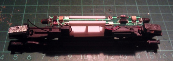
The new projects are going to use Con-Cor’s 4500 Gas Turbine chassis as pictured below.
This bulky chassis is also used for Con Cor’s U50 model. It has a single motor which powers two of the four trucks. The two inner trucks are dummy trucks but don’t let that fool you into thinking it is underpowered, all the mass of that metal chassis makes it a good puller.
To start with I modeled the main chassis as one piece, originally thinking it would work without modifications. However once I began to see the difference it would create in the new shell I decided it had to be drawn properly.
So I then split it down into the two halves as shown below, taking note of all the lumps and bumps, so that when I design the extension piece it should be a good fit.
I have also drawn the drive shafts, these will also need to be modified or extended as they will be 5mm further away from the motor. Extending these should just be a case of 3D printing a part that plugs into the end of the gear socket.
To make sure the chassis extension piece will fit correctly I have also drawn the motor, this is represented as a fairly basic block with the drive cogs protruding from it. This is because all I am really interested in is its size and contact points with the chassis.
With all the necessary parts drawn I can assemble them in the 3D model as shown below. Having all the parts in place makes it easer to see how to design the chassis extension.
The two halves of the chassis are separated by plastic strips, as shown below, which I have drawn in as these too may be affected by the extension. I choose not to draw the screws that hold it all together as they should not be affected and, after all, I still have the new shells to draw yet.
Here it is all assembled in the 3D model ready to start designing the new extension modification.
On the current chassis the two inner trucks have a center to center dimension of 51mm and for the first new model kit it will need to be 62mm. Because the center of the chassis will be remaining in the same location it will need to expand by 5.5mm in both directions. I will share with you how I have made the extension in a later post but for now here is a quick screen shot of one of the new shells in the very early drawing stages.
A few weeks ago I shared with you my designs for a dummy chassis and trucks for all those spare Atlas N Scale C-628/C-630 shells, you can find the post here. In this post I will show you how the 3D printed parts came out and how they all fitted together.
Below is a rendering of the finished assembly including power pickups and lighting board.
The power pickups will be in the form of axle wipes as shown in the rendering below.
All the parts, with the exception of the circuit board clip, are printed in Shapeways’ Frosted Ultra Detail material and once cleaned I sprayed them with a basic locomotive black.
The wipes are made from 1mm wide phosphor bronze strips. This material is ideal for wipes as it is strong, flexible and has excellent electrical conductive properties. To make the wiper I cut four strips of phosphor bronze; two measuring 27mm, one at 8mm and one at 6.5mm.
Before I soldered anything together I test fitted the parts, as shown below. The 6.5mm long strip is the cross-piece, it is slightly longer than it needs to be but I will trim it once I have soldered the parts together. The cross-piece will fit under the two main wipers. I repositioned the parts and marked the main wipers where the parts intersected with a cutting knife.
I then soldered the first two pieces together ensuring they where perpendicular to each other. I didn’t solder the other wiper strip on at this point because if it is not in the right place it will not slide between the wiper guides on the truck adding unnecessary drag on the axes.
To get the other wiper in the correct place I added some solder to the cross strip end then I positioned the first pieces in place. Then I placed the second wiper in place and very quickly used the soldering iron to join the two parts. This has to be done quickly because as the phosphor bronze has great electrical conductive properties this also means it conducts heat very quickly. The FUD material has a low melting point so if the iron is left on the joining for too long the phosphor bronze will start to sink into the truck.
Once the parts are joined they can be removed again and the solder joints can be renforced if required. The cross strip can also be trimmed back; if it sticks out too far it may snag the center wheel set. The last part to add on is the 8mm strip which needs to be soldered to the center of the cross strip. Ideally it wants to be parallel with the wipers but it can be at a slight angle as again, if the iron spends too long on the joint the heat will quickly travel through the phosphor bronze strips and release the other joints.
Once all the joints are soldered the 8mm strip needs to be bent up by 90° ensuring, as shown below, that the cross strip is above the 8mm and wiper strips.
After another quick test fit the wiper assembly can be glued in place. For this I like to use Loctite’s Gel Control Super Glue, because it is a gel and so will not run all over the parts and it also gives you about twelve seconds to position the parts before it sets.
The super glue only needs to be applied under the center strip, the main wipers need to be able to flex.
Once the wipers are fixed in place the 8mm strip will now project up through the slot in the truck next to the bolster pin hole. This will now become the contact point to attach the wires.
The next step is to fix in the wheel sets, the center set will be electrical neutral as it does not touch either of the wipers. However it is still recommended to install it in the same orientation as the other two, that is to say that all three wheel sets have their electrically isolated wheels on the same side. Although my 3D printed trucks have been designed to have the wheel sets fitted from the underside, the two outer wheel sets can be fitted from above, this will cause the wipers to flex naturally without being bent to get them in.
Once fitted and the wheel sets have been checked to see if they move freely they are ready to be fitted onto the chassis.
When pushing the bolster pins into the chassis be carefull not to break the chassis. Once the trucks are fitted thin wires can be soldered to the contact points which will be poking through the crescent shaped slots in the chassis. At this stage I realized that only 8mm for the last strip made it a little bit tricky to solder the wires on, so on the next chassis I will make that strip 12mm long. Even with all the parts assembled the chassis is extremely light and needs to be weighted to both improve the electrical contact with the rails and to ensure the locomotive will stay on the track. Again I have used old motorcycle wheel balancing weights which are smaller than car ones and are ideal for N Scale.
I also filled the fuel tank with weights which made the chassis the ideal weight overall. The clip which holds the circuit board is made from Shapeways White Strong & Flexible material. It is a lot cheaper to print than the FUD because it is a coarser material, this is ideal as the parts don’t need any visible detail. The two halves are the same as each other and clip together securing the circuit board in place between them. The assembly then clips into the chassis above the fuel tank. The wires can then be soldered to the circuit board as shown below.
The next step is to mount the shell, below you can see a pair of Alco C-628 locomotives in the Monon livery. One is powered and one is the dummy. I would have asked if you could tell which one was which but I think my mistake with the truck colour gives the game away!
Both locomotives light up in the same way, the final step is to run them on a layout and I will share with you how that worked out in a later post, but for now Merry Christmas.
This week’s post will be a short one as my wife has got us tickets to see the new Hobbit movie, so I am off to the cinema, but I promise I won’t give any spoilers! Last week I shared with you my new 3D printed O Scale UP water tenders for the excursion train, you can find the post here. So this week I will share some of the work I am doing on the tenders, starting with cleaning them up.
The tenders have been printed in Shapeways’ Frosted Detail material. Models printed FD or FUD (Frosted Ultra Detail) have a waxy residue and need to be soaked in Bestine, Goo Gone or somthing similar. This leaves a powder on the surface which is the dried up wax residue. I have also found that models in FD have more powder than models in FUD. To remove the powder on my N Scale models I normally use a soft toothbrush and gently scrub the model. This does not always remove it all, particularly from the difficult-to-reach areas. To get over this I have a soft brush that fits onto my mini drill, similar to a Dremel tool. With the large surface area of the O scale tenders this made the job much faster and helped me get into all the tricky areas such as around the grab-rail posts. These can be delicate and the toothbrush has an increased possibility of knocking them off.
With all the loose powder removed any areas showing evidence of the printing process become clear. On these particular models it was on the curved ends. You can see in the picture below that there are ‘veins’ running down the end of the tender.
These are actually plastic and attached to the model. To remove these I use my mini drill again with a small sanding stone bit; because it is tapered it allows me to get the flat surface across the face of the model. The trick here is a little bit at a time, if you go at too hard it is very easy to remove too much.
Once the area is ground flat, I use the soft brush bit again to remove any new dust. In the picture below you can see the finished surface. It is smooth to the touch. You can still see the marks where the ‘veins’ were but these will disappear when the model is painted.
Painting the tenders will be the next step and I will share that with you in a later post.
This post is about my largest print project to date.
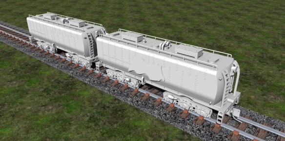
Back in February of this year I started telling you about my designs for an N Scale 3D printed Union Pacific excursion train water tender; you can read that first post here. The design for the 2007 to present day configuration of these tenders was very successful and below is a photo of a pair of N Scale tenders running behind a UP Challenger class locomotive.
Then, at this year’s National Model Railroad Association (British Regions) Annual Convention, I introduced my HO version of this tender. Below you can see it running with a Brass UP 844.
This is currently my largest 3D printed item, and I’ve had two of them printed. Both Jim Adams and Joe Jordan.
As usual the project starts with a 3D model, as shown above. For the O scale tender I was able to take the HO model and rework it. I could have used the HO model as it was but this would mean the material would have been twice as thick as it needed to be and although that would have made it very strong it also would have made it very expensive. Shapeways, and other 3D printing bureaus, charge by material volume to produce prints.
This model will also be different to the HO and N Scale kits I have produced because I will not be supplying a chassis or any trucks with the kit. This is because these are available from Lionel as spare parts for their Union Pacific Water Tenders: you can find the parts here.
Here are the Lionel chassis assembled with truck and couplers.
Using these chassis has two great advantages, the first being that they are cheaper to buy than to have 3D printed, and secondly, they are very heavy and strong. This is important because in O scale the load which is put on to the couplings and chassis is immense compared to HO and N scale trains. These metal chassis will take all the strain.
The trucks still need to be removed and disassembled so they can be sprayed silver to match the UP tender in its Armor livery.
The other detail parts which I will be using on the O scale tenders, as seen below, are cut levers, cut lever support brackets, and brake wheels on stands. On my N & HO scale tenders these are part of the 3D printed body. (Cut levers are used in the US on the ends of most rolling stock. It is a lever which allows railroad workers to manually release the couplings between the cars and cutting the train, without going between the cars).
Having the cut levers and their supporting brackets as separately applied details for this model was very useful. If the cut levers had been 3D printed it would mean that the print would be too long for the printer, it really was that close. As they are now separate parts the reduction in length at each end was just enough and the model now fits.
The handrails on top of the tender can also be printed in situ as they are twice as thick as the HO ones and consequently a lot stronger; if the HO handrails are printed in situ there is a good chance that they will be broken in the cleaning and shipping process.
Below you can see all the parts as they are delivered from Shapeways.
Detail parts such as the ladders, tool boxes, flag plates and headlights are still printed as separately applied parts. This helps with painting and finishing the model.
These tender kits have been printed in the Shapeways Frosted Detail material. This has a layer thickness of 32 microns and although it is not quite as sharp as the Frosted Ultra Detail at 29 microns in O scale none of the detail is distorted or missing.
The main test for the shells was to make sure they fitted onto the Lionel chassis, and they dropped right on. The tool boxes on top of the tenders in the images below have already been cleaned ready for painting which is why they are opaque.
The next step is to clean up the main bodies ready for painting. This was a bit more tricky than normal as these are somewhat bigger than my normal 3D printed objects. To give you an idea of just how big they are in O Scale, below is a picture of the N Scale tender with the HO one…
…and then again with the O Scale one behind.
With the second O Scale tender in the mix the scale of these starts to become clear.
Cleaning the O Scale tenders is going to need a much bigger container!
In a later post I will share with you the finishing process and photos of the completed tenders with all their detail parts applied ready to make their way to their new owner.
With the launch of my most recent locomotive shells, the Baldwin RT-624 and the popular Baldwin DT6-6-2000, there must have been a lot of surplus shells left over from the donor locomotives. In this post I will share with you a new product that will allow these spare shells to be used.
Both the RT-624 and the DT6-6-2000 use the same donor chassis from an Atlas C-628 or C-630, it’s the same chassis in both. Here is one of my C-628 locomotives that sacrificed it’s chassis for my first DT6-6-2000.
The shells on these locomotive are very nice and it would be a shame not to use them. The huge fuel tank and truck side frames are also not required as donor parts which means the bulk of the locomotive is intact. Here is the locomotive disassembled.
Re using the trucks or side frames would be a bit tricky as they are designed to clip onto the Atlas power truck but the main shell and fuel tank can easily be reused. For this a chassis is needed. For my DDA40X dummy chassis I used Shapeways White Strong & Flexible material as it has a low-cost for volume and that a was big chassis. That dummy chassis was fairly simple and did not need a lot of detailed sections so the courser WS&F was not a problem. For the C-628 chassis I will be using Shapeways Frosted Ultra Detail material. This is because it allows for very accurate detail and that will be needed to replicate the same fixings points used on the original chassis.
To start I used the 3D model chassis I created to fit the DT6-6-2000 shell on to, as shown below. The chassis is modeled at the right hight from the rail head and I have included all the groves and bumps. The C-628 cab fits over the lower section on the left. The fuel tank clips onto the horizontal slot as well as having fins that fit into the vertical slots, they are not centered so the fuel tank will only fit on one way round.
Next I created a chassis model using as little material as possible whilst retaining the strength, the material is not as cheap as the WS&F and very light so there in nothing to be gained by bulking it up at this stage. Weight will need to be added but as the fuel tank is hollow, with a bottom, it can be filled with scrap bits of metal.
Next we need some trucks. I copied the side frames from the atlas trucks, and added a bit more detail from photographs of the real locomotive as shown below. The raised section around the hole is the pivot point where the bolster pin passes through the truck. Normally the pivot point is in the middle of the truck or over the center axle, but this would create two problems. Firstly the center wheel set would need to be removed every time the truck needed to come off and secondly as the truck rotated it would hit detail which hangs down from the atlas shell.
The underside of the truck has four sets of forks sticking out of the middle. These have been designed to allow 1mm phosphor bronze, or similar, metal strips to be fixed to the truck and make axle wipers. The forks stop the axle wipers from touching the wheels and causing a short circuit. The forks can be seen in the image below as well as a slotted hole in front of the bolster pin hole.
The image below shows the ‘H’ shaped set of axle wipes fitted to the truck as well as the wheel sets, I am using Fox Valley metal wheel sets that have one insulated wheel. The two outer wheel sets pick up power from one rail and the middle wheel set is electrically neutral. The wipers are made from four strips of phosphor bronze and once soldered together will be glued into the truck.
With the truck set back on the track you can see the fourth strip of phosphor bronze poking through the slotted hole, the bolster pin is also visible in the image below although it would drop out of the real truck without being pushed into the chassis.
Both trucks are the same but as they are asymmetric one is rotated by 180° as you can see below. There is a crescent slot at each end of the chassis to allow the phosphor bronze strip to stick up without preventing the truck from rotating
You may be wondering why I have added electrical pickups to a dummy locomotive, well as all of my DT-6-6-2000 and RT-624 locomotives have been converted to DCC the old circuit boards are also surplus. I intend to use some of my dummy C-628 locomotives as pushes on the rear of long trains and they need to have lights. As the circuit board puts the mounted LEDs in the right place it makes sense to use it. However as you may remember from the view of the 3D modeled power chassis the circuit board sits along way up from the top of my 3D printed chassis. To solve this I have designed a pair of circuit board clips as shown below.
These are printed in Shapeways WS&F material so they are really cheap, they are designed to clip together holding the circuit board in place, then they clip into the 3D printed chassis as shown below.
The last thing to do is run a wire from the phosphor bronze strip to the power connection on the circuit board. If run as is on a DC locomotive the lights would work just as they did with the power chassis fitted. If the polarity of the wires is reversed and the LEDs swapped for red ones this will work as tail lights. A DCC light decoder could be fitted or even a sound decoder.
I have already printed this dummy chassis and it was fairly successful, the issue I had with the kit was some of the detail on the truck was catching some of the detail on the shell. With a bit of cutting and filing the problem was solved. Here it is pushing behind a long coal train on Ant Quinlan’s wonderful layout, Horsethief Bridge, at the NMRA (BR) convention 2014. You can read more about the layout here.
Until the alteration was made, it struggled on tight curves but that was soon fixed, Ant and I also experiments with adding weight to the shell, we found 3 bolts was just about right!
The added weight gave the dummy stability and it tracked round the layout well. Below is a video of it running behind the coal train as a pusher.
And here is another video of it working as a mid train helper. Ant’s rolling stock was all weighted so there was a fair tonnage being pulled through the dummy locomotive but it did the job without trouble.
Since the first 3D print was tested I have corrected the issues with the clashing details and fine tuned a few other areas. The next 3D print has been ordered and should be here later this week. In a later post I will show you step by step the assembly of the axle wipers, adding weight, painting and finishing the dummy locomotive. The dummy chassis kit will then be made available for anybody that wants to use their spare Atlas C-628 and C-630 shells.


 Once the wipers are fixed in place the 8mm strip will now project up through the slot in the truck next to the bolster pin hole. This will now become the contact point to attach the wires.


 With the large surface area of the O scale tenders this made the job much faster and helped me get into all the tricky areas such as around the grab-rail posts. These can be delicate and the toothbrush has an increased possibility of knocking them off.


 Using these chassis has two great advantages, the first being that they are cheaper to buy than to have 3D printed, and secondly, they are very heavy and strong. This is important because in O scale the load which is put on to the couplings and chassis is immense compared to HO and N scale trains. These metal chassis will take all the strain.


 The main test for the shells was to make sure they fitted onto the Lionel chassis, and they dropped right on. The tool boxes on top of the tenders in the images below have already been cleaned ready for painting which is why they are opaque.


You must be logged in to post a comment.