This week I have another new replacement part to share with you for the N Gauge Minitrix 9F. I’ve already made replacement parts for this locomotive such as the eccentric rod crank pin which you can read about here and the cross head, which you can read about here.
The Minitrix 9F has always been a good runner but, apart from the eccentric crank pin and cross head, it suffers from wear in the plastic gear after lots of running.
The worm gear on the motor shaft is metal and drives a plastic gear, this in turn drives two metal gears which drive the metal gears between and on the axles. The first gear is made from plastic, I believe, because it’s a double gear and it’s cheaper to make it in plastic than metal. A double gear means it has a large and small diameter gear moulded into one piece as illustrated below.
Because the original gear is plastic and is driven by and drives metal gears, over time it wears down and looks like this.
Sometimes a slight wear can be overcome by slipping a pack under the rear of the motor, tilting it forwards, causing the worm gear to push down onto the plastic gear but eventually it will wear out.
You can see the larger gear, which is driven by the worm gear, has lost its points and the bottom left side has worn more than the rest. This may be because the side rods jammed, stopping the gear, but the worm gear carried on turning, chewing the plastic.
The new 3D printed part, as shown below, is printed in Shapeways Fine Detail Plastic. This is a hard material and long-lasting which has been proven with the O Scale gears I made a few years ago. You can read more about those here.
The plastic gear spins on a metal axle which fits into the new gear without enlarging the hole.
Fitted back into the chassis before the motor is re-fitted, the new gear can be seen in the top of the tower. At this stage the gear can easily be tested because the worm gear is not stopping all the gears from turning. Running the wheels along the work bench turns all the gears, including the new one.
With the motor re-fitted, along with the weights and shell, the locomotive can be tested on power and it runs nice and smoothly.
This week’s post will be a continuation of my step-by-step build of an N Scale A-B-A ready-to-run set of Alco C-855 locomotives, and will be concentrating on reassembling the trucks and pilots now they’ve been painted. You can find part one of the build here.
In last week’s post I stripped down the trucks and pilots ready for painting and below you can see all 12 trucks now in shiny silver. They’ve been sprayed with Humbrol enamel paint.
To reassemble I start with one of the inner trucks. These are not powered and simply track along behind, or in front, of the lead truck forming the span bolster. A ‘span bolster’ is the name given to this configuration of trucks. On the prototype they’re linked together by a beam which is connected to the locomotive at one rotation point, allowing the truck to articulate. Together, the trucks form one big truck under each end of the locomotive. Having the trucks individually fixed to the locomotive would make it harder to negotiate corners.
The wheels have points on the end of the axels and simply press into the truck which has holes for the points. You’ll need to pry the sides apart slightly to allow the points to drop down into the molded holes. If the wheels don’t spin freely they’re not in the right place.
The powered truck fits over the peg on the trailing truck.
The metal weight is then fitted over the wheels. Once fixed in place this will also stop the trucks from separating. The metal weight is important as it stops the unpowered truck from jumping the track and derailing the locomotive.
The weight is held in place by one screw on the underside.
This can then be repeated for each set of trucks, six in total for the A-B-A set.
The pilots are painted in UP Harbor Mist Gray. I used Tru-Color paints for this.
The front of the chassis is slightly easier than the rear as there’s less to reassemble. The truck center is as we left it with the black coupling pocket positioned between the metal halves, holding them in the right place.
This particular chassis is for the C-855B and I’ll be using Uni-Mate couplers between the A-B-A set. These give a great coupling which can’t be uncoupled without lifting the locomotive. The Uni-Mate fits into the pocket with a spring as shown below. This is the same fitting as the original Rapido coupling, and a Micro-Trains knuckle can also be fitted in the same way, which I’ll be using on the two A units.
The front pilot can then be fitted over the truck which also holds the coupling in place. It will click in as the pegs find their positions.
The rear of the chassis is similar but the pilot fixes on from above the truck (behind in this example as the chassis is upside-down).
By squeezing the metal halves slightly together the pilot will fit over and the two locating pegs should clip into place.
The coupler pocket can then be pushed in-between the halves acting as a wedge, clamping the pilot in place.
Again I have fitted a Uni-Mate coupler as this is the C-855B.
To stop the coupler falling out the U-shaped plastic clip fits over the pocket holding it all in place. The geared wheels can then be replaced. If, as below, your model had the brass wheels wipers, don’t forget to put them back in, ensuring the wipers are behind the wheels.
The trucks can now be fixed back onto the chassis and held on using two screws in each end.
With all three chassis reassembled with their new silver trucks my attentions can now be turned to painting the shells, which is a time-consuming project and I’ll be covering that in another post soon, but just as teaser here’s one under way.
One thing I will say, having painted this shell we’ve really seen a difference in the quality of the 3D printing, not only in the improved detailing in the model but also the paint adheres really well. The flat surfaces are very smooth, and all together this makes for a great model. It’s rewarding to see the developments that have taken place in 3D printing, especially when we can pass those benefits onto you.
This week’s post will be a continuation of my step-by-step build of an N Scale A-B-A ready-to-run set of Alco C-855 locomotives. And this post will be concentrating on the trucks and pilots. You can find part one of the build here.
Now the chassis are all ready, stretched, notched and DCC fitted as shown below, we need to turn to the cosmetic parts.
The three chassis supplied for this build came from locomotives painted in different railroad liveries and consequently the trucks and pilots are all different colors. And the one at the bottom of the image below has been weathered.
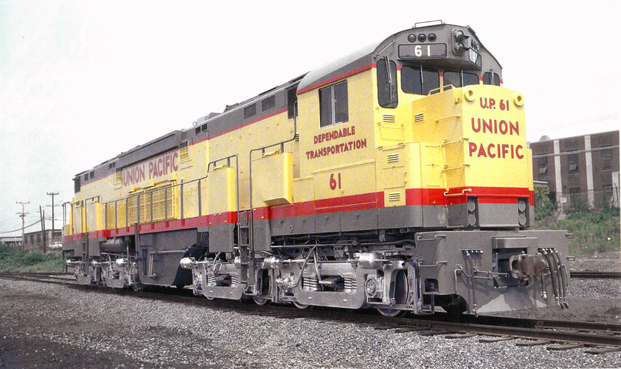
The C-855 has silver trucks and UP Harbour Mist Gray pilots as you can see in the photo below. (Taken from American-rails.com).
The truck assembly is fairly straight forward. The two screws on the front truck hold both trucks to the locomotive.
The front truck side frame and rear truck then lift off leaving the wheels behind.
Inside the rear truck is a metal weight which holds the wheels in place.
The weight is removed by taking out the last screw. This also separates the two trucks.
The wheels are fixed between the truck side frames and can easily be removed by gently spreading the side frames outwards until the wheels pop out.
Next we have the pilots. The front pilot is a plastic molded section which is clipped over the two metal truck sections. The truck is in two sections to electrically isolate each side.
On the top are two tabs which can be pushed apart and the pilot drops down. This also releases the coupling and spring so make sure it doesn’t fly off.
The rear pilot has a similar plastic molded section but this time it fits on the top of the truck sections. There is an extra clip which fits under the pilot to hold in the coupling and spring. In the picture below I have removed the clip.
The coupling, spring and spring box is then removed as shown below.
Lastly the rear pilot can be slid off the truck sections.
The two sections as shown below are ready for painting as are the four truck side frames.
The painting will be covered in a later post as will the re-assembly of the trucks where I will cover changing couplings.
For those of you who’ve been reading my blog for a while you may remember a post I did in 2015 about the ‘Great Dorset Steam Fair’ (GDSF), also now known as the ‘The National Heritage Show’. You can find the post here.
This year I paid the GDSF another visit, and not just because it’s a great show, but because they were celebrating their 50th anniversary and to mark the occasion they decided to attempt a Guinness World Record for the ‘the largest display of steam-powered vehicles’. And they did it; out of 522 full size steam engines present at the show, 472 were officially recognised as meeting the set criteria. I’m not sure what the criteria were but they made for an impressive display and something which will probably not happen again for a long time.
As well as the 522 full size steam engines the show was full with everything from horse plowing to diggers and to try to get around to see them all in one day was simply not possible, so I’m going to share with you some of the highlights for me as well as some of the full size steam engines in the show.
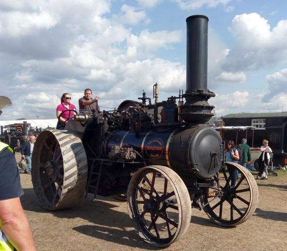
Arriving very early helped as a lot of the engines, although parked up, were getting under steam and I was able to walk up and down the rows. Several of the engines I’ve seen before but what also made this show more special was the GDSF had shipped in many from around the world.
Fowler Road locomotive ‘Atlas’.
Foden Road Locomotive ‘Earl of Dudley’.
This was one of several shipped in from New Zealand. Foden Road Locomotive.
This unusual, to me anyway, engine ‘Peerless’ was made by Peerless, Geiser Mfg. Co., Waynesboro, Pennsylvania, USA.
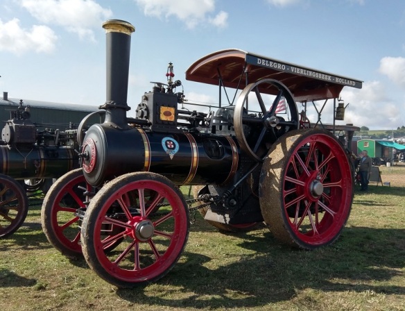
This Ruston Proctor & Co. road engine came from Holland.
Fowler General Purpose Engine “Kinsale”.
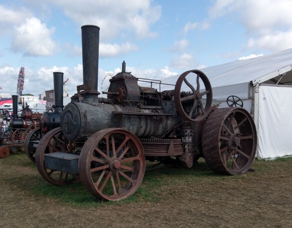
This Ruston Proctor & Co. traction engine.
Fowler Road Locomotive ‘The Great North’.
This plowing engine, significant for its longer boiler to accommodate the winch wheel, was in need of restoration but I feel confident it will be back in steam at a future GDSF.
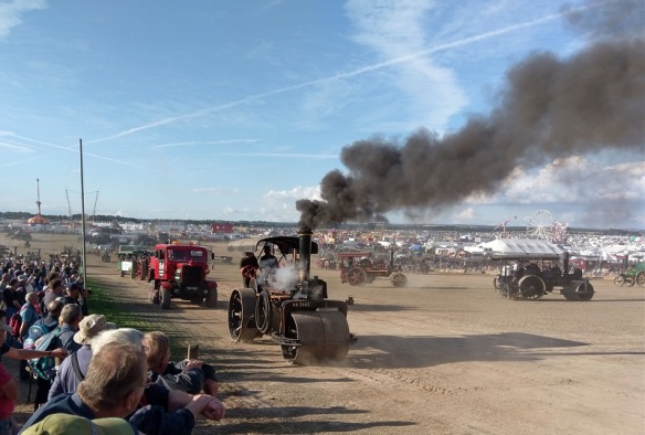
Of course seeing the engines up close is great but it’s not as good as seeing them working and the GDSF does just that. There are several arenas across the show but the largest and my favorite by far is the heavy haulage ring, more commonly known by the fans as the ‘Play Pen’. Here you can see engines of all sizes working up and down the hill, running light or towing trailers of varies sizes and weights.
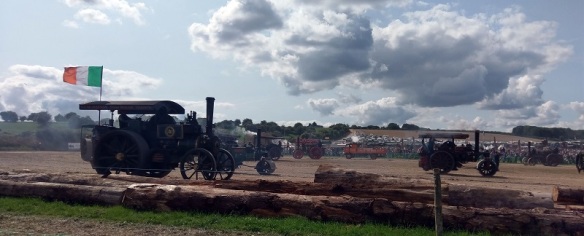
This Irish road locomotive was getting some good exercise.
This German engine was heading into the ring for a good run.
Even better than one traction engine is two and in the video below you can see the 1906 Burrell Traction Engine (BP5913) “Validus” working with the Burrell Road Locomotive (TA615) “Semper Fidelis” to pull a load of chains up the hill. I think the driver of “Semper Fidelis” is having a bit of fun as he’s allowing “Validus” to do all the work untill “Validus” realises what’s going on and calls for some more power. Together they accelerate up the hill.
As well as traditional style engines I was pleased to see some things I’d never seen before. One of these was ‘Avery’.
This American design undermounted tractionengine looks very much like a railway locomotive. The crew, when interviewed over the PA system, said when driving you can’t see over the boiler, just like a train. I believe they said they’d it brought over from Oklahoma.
The cab also had the same shape and feel as a railway locomotive.
The ‘Avery’ was build by Avery & Co, Peoria, Illinois, USA.
But the best bit, for me, about the ‘Avery’ was the wonderful American chime whistle which you can hear towards the end of the video below.
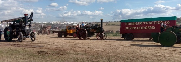
The ‘heavy haulage’ ring is also used for just that and Allelys brought one of their big tractor units and trailers with a BR standard class 5 locomotive on the back.
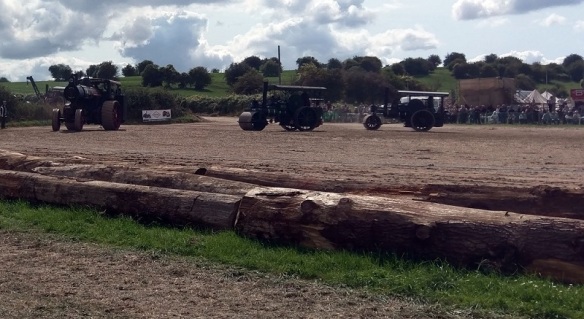
As well as demonstrating throughout the day how they load and unload the locomotive they also allowed the setup to be towed around the ring and below you can see three road locomotives doing a lap of the lower ring. The modern tractor unit is simply providing air for the trailer brakes.
There is always a variety of different loads to tow in the ring; below is a large cylinder spanning between two trucks.
And a well trailer with a large transformer.
Below we have two road locomotives working a generator load up the hill.
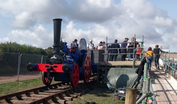
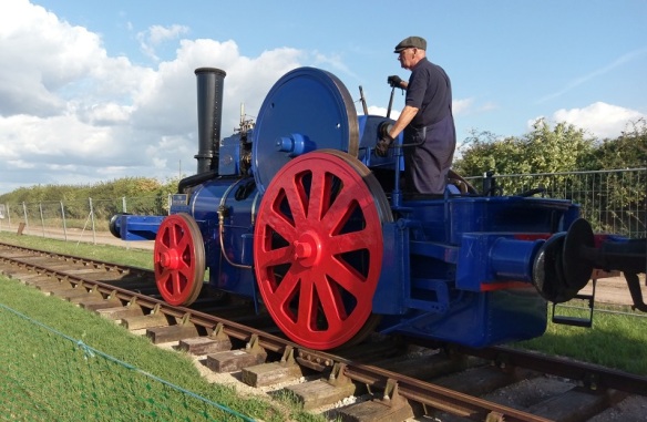
Railway locomotives and traction engines, although evolving at the same time, normally took very different paths and I was surprised to see a traction engine railway locomotive.
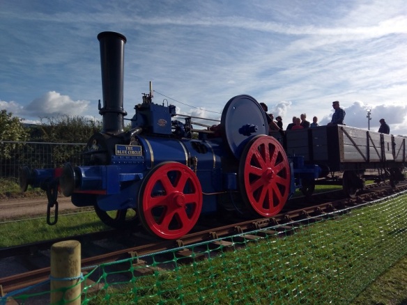
‘The Blue Circle’ was built by Aveling & Porter in 1926 as was the very last one they built out of 130 and is believed to be the only one left. It was originally purchased by Holborqugh Cement Co. Ltd of Kent which later became associated with Portland Cement. It was used to shunt cement and coal trucks around the works.
The locomotive worked right up until 1962 when it was replaced with a more powerful locomotive. In 1964 it was presented to the Blue Bell Railway for preservation and it was at this point it was named “The Blue Circle” after Portland’s popular cement products. However due to its relatively low power, for a railway locomotive, and top speed of 6 miles an hour, it didn’t get returned to service. But in 1988 it was sold to its present owner and returned to all of its glory.
‘The Blue Circle’ was giving wagon rides at the GDSF and I was really pleased to see it preserved and working.
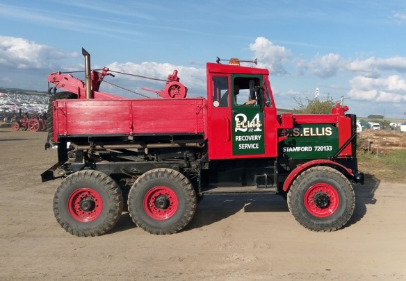
As well as steam engines I also like a lot of the historic military and commercial vehicles but for me there’s one which sits at the top of the list, the Scammell Explorer.
“Chunky” here doesn’t have a broken axle, it’s just parked on a ramp showing off its amazing suspension.
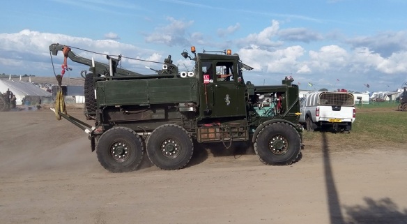
These 6 by 6 tank recovery vehicles are right at home charging around the “Play Pen”.
Here’s one as it went up the hill.
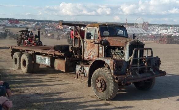
There were, of course, lots of other commercial vehicles but this one stood out; I don’t know what it was but I think Mad Max might like it!
This is an Ex-Russian military heavy haulage truck.
As you can see, it’s a lot bigger than the Scammell Explorer which it was towing.
And just to show off, below you can see and hear it towing two Scammells up the hill.
Another unusual traction engine was this reversed boiler direct plowing engine.
This engine, named ‘Joker’ was built by Garrett ‘Suffolk Punch’ tractor in 1919. As stated it was designed for direct plowing, which is basically towing a plow, and was geared to be faster than traditional traction engines. Traditionally plowing had been done with two engines, see the 2015 GDSF post to read more. From what I understand this design was introduced about the same time as diesel tractors started to come out and the traction engines were seen as old technology so the design never took off.
Steam rollers are also a huge part of the GDSF and although they have their own areas where they where building roads, there were plenty in the ring.
These also provide a great service as the ground, although dry, still gets churned up by all the heavy equipment and the rollers simply smooth it all out.
Steam lorries can always been seen in the ring and this year was no exception.
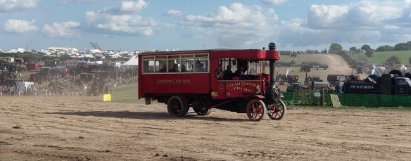
But for me it was the steam Omnibus which stood out; a little different and one I’d not seen before.
A unsuall steam roller I managed to snap as it passed by me was this ex-Wirksworth Quarries chain-driven Dual-Roller.
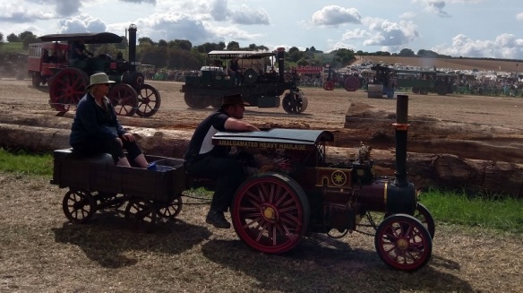
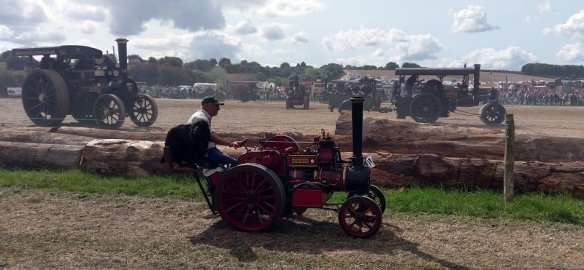
On display alongside the full size steam engines there are lots and lots of miniature engines and here are few as they trundled by.
I think the dog is in charge of this one!
This miniature steam lorry fire engine was fun.
Leaving the heavy haulage ring for a minute over in the threshing section, which sadly I only had time to pass by once, was a Canadian engine working the thresher.
And if you wondering what a thresher looks like, here is one powered by an Allchin tractionengine ‘Evedon Lad’ built in 1910.
If you’re wondering why I didn’t get a chance to look around the rest of the threshing area, here is a view of just part of the site taken from near the top of the plowing field.
This panoramic video is taken from the same spot and shows half of the GDSF site. The rest is to the right of the hedge.
One of the big attractions, and always has been, is the Showmans’ engines.
This Showman’s from Ireland was looking striking in green.
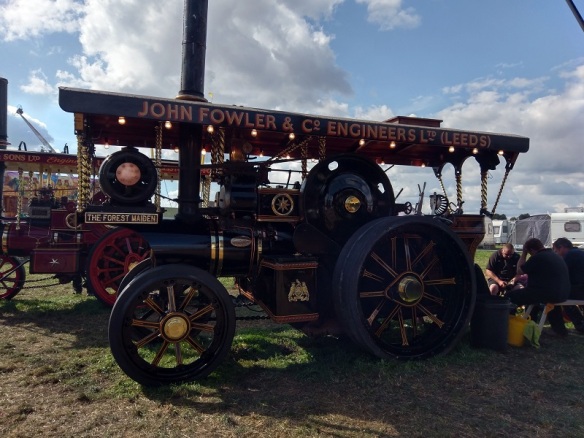
‘The Forest Maiden’ which has been a regular visitor to the show over the years was previously red has now been repainted in glistening black with the name of the builder returned to the engine.
And given how many there were at the GDSF this year it wasn’t surprising to see some running in the ‘Play Pen’.
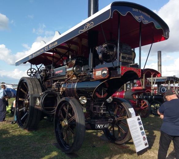
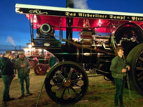
This Showman’s engine “The Iron Duke” was brought back from Germany where it had been powering an amusement park.
On the right side the German writing is translated to English and reads ‘the fascination of steam’.
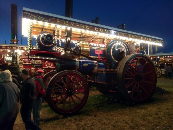
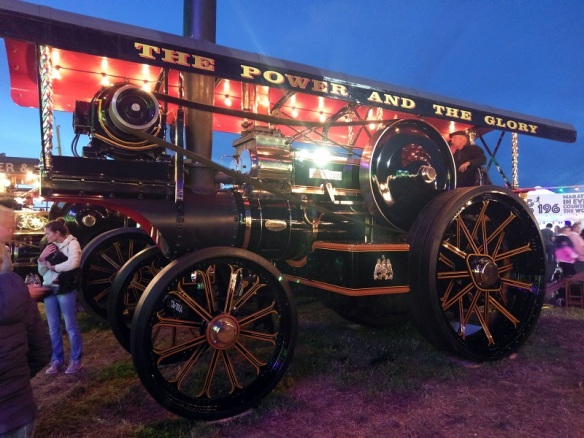
As the evening draws in the Showman’s engines comes alive with electric light and demonstrate how they got their names – by powering the historic fairgrounds.
If you get a chance to visit the GDSF it’s very much worth staying on to see these engines come into their own in the evening; the lights, steam, smell, noise from the fairground and friendly crowds enjoying the atmosphere with a pint of real ale is an experience not to be missed.
As I said earlier there was just so much to see it was impossible to capture it all but here are some of the other engines doing what they do best.
One of my favorite parts of the show is when it starts to get dark but some engines are still running around the ‘Play Pen’ and this year we had a good sky and a full moon. You get a real sense of the enjoyment the drivers have at running these engines; the crowds have died down but they’re still making the most of having the space to let them run.
Here are some videos of engines running in the dark.
The GDSF is always a special event because a lot of the engines spend the event working as they were built to do and not just sitting as museum pieces. Next year’s show may not be as big but it’ll still be an impressive sight giving all the noises, smells and wonders of steam and I hope to be there; maybe I’ll see you at the heavy haulage ring!


You must be logged in to post a comment.