Adding Lights to an Alco C-855 in N Scale

This week I have moved my C-855 project on a little bit further by adding lights to the locos so in this week’s post I will show you how I did it.

As with any modeling project there are several ways to do the same thing but this method works for me.  The C-855 has a pair of headlights centered above the cab windows, one above the other.

C-855 WIP 6

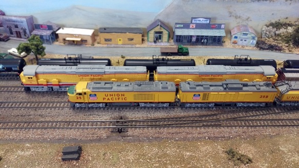
There is also a rear facing light, offset on the right hand side, but I have chosen not to illuminate this because these C-855s will always be running together so the rear lights would never come on.

When I made the 3D model I allowed room in the cab roof for an LED; I even recessed the roof to accept a 2mm LED directly into the back of the light as you can see in the section image below.

Alco C-855 Inside cab (Render)

However, for this particular loco I used an LED from a DC lighting board.  Having used lots of Atlas C-628 & C-630 chassis for my DT6-6-2000 & RT-624 projects I have several of these boards knocking about.

C-855 Lighting 1

There are a few reasons for using these. The LED is the right color, there is a resistor already attached and the LED is shrouded by a rubber sleeve.  This LED is a 3mm so it won’t fit into the hole I designed in the roof but I’ll deal with that later.

The only parts of the lighting board I really need are the LED and resistor; and only one end has these close together.  Using a pair of side snips I cut off that end just behind the yellow capacitor.

C-855 Lighting 2

Then I cut the resistor leg furthest from the LED and rotate the resister by 90 degrees.

C-855 Lighting 3

Then, to make access a bit easier, I remove the capacitor and diode from the circuit board.

C-855 Lighting 4

Lastly I cut the unnecessary part of the circuit board away, leaving me with just the parts I need.

C-855 Lighting 5

The inside of the shell is still white as only the outside was painted.  This can cause a small problem as the material is fairly light porous so any internal light will show through or cause the shell to glow.

C-855 Lighting 6

To prevent this I painted the inside of the cab roof black with a basic matte black paint.  Only the roof and area around the hole for the light to shine through needs to be painted.

C-855 Lighting 7 C-855 Lighting 8

With the shell prepared the next step is to connect the wires.  The blue wire from any DCC decoder is the positive and for this configuration it’s connected to the LED.  The negative white wire, front light, is connected to the resistor.  It’s worth checking at this stage that the LED works.  Don’t forget that an LED is still a diode and if the wires are round the wrong way it simply won’t work.  Once you are happy that the LED works I would recommend putting a strip of Kapton Tape between the wires.  If they touch you will damage your DCC decoder.  A better option is to cover both the white wire and resister connection with heat shrink but you need to remember to put the heat shrink over the wire first.

C-855 Lighting 9

The light assembly is then glued into the roof of the cab.  I used superglue for this as it’s fast and I know it has no adverse effects on the shell material.  The LED wants to be right up tight to the hole in the front of the cab to reduce the amount of light that spills out into the cab.

C-855 Lighting 10

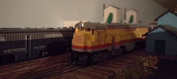
This is another good time to check that everything is working correctly.  As you can see the headlights are fine but there’s a lot of light in the cab.  This is coming from the area where the sleeve over the LED does not go all the way to the end.  It’s also reflecting around the rest of the white cab walls.

C-855 Lighting 12

So to solve this I then paint over the LED assembly with the same matte black paint.  This particular paint is a fairly old pot and has started to thicken up, which is perfect.  I’ve applied a thick coat and used the paint to seal the gap between the LED and the cab front.

C-855 Lighting 11

Once the paint had dried the body shell is refitted to the chassis, checking that the two wires don’t get trapped between the sides, and the loco lights are re-tested.

As you can see there’s still a bit of light showing through on one side of the cab but the headlights are working well.

C-855 Lighting 13

To fix the light coming into the cab I removed the shell and gave the LED assembly another liberal coat of matte black paint which did the trick

C-855 Lighting 14

The head light is now complete, but there are some more details to apply to totally finish off the loco and I will cover those next week.

N Scale Alco C-855’s Out On The Mainline

Last weekend I was at the Fordingbridge Model Railway Exhibition with our club layout, ‘Solent Summit’.  I’d planned on giving a full review of this very busy exhibition in this week’s post but, as we had a fairly large layout to assemble and run this year, I didn’t have time to have a good look around or take photos of the other layouts.  However I did manage to capture some shots of a pair of freshly painted locos out on their first trial run.

C-855 WIP 1

Locos 60 and 61 are still at the ‘work-in-progress’ stage.  The main painting and lining has been done by our friends at Model Railway Solutions but they still need their handrails adding, trucks painting and to be weathered up.  As you can see below even though the shells have been printed in Shapeways FUD material, which isn’t as sharp as the FXD, the detail has come out very well.  The lone handrail was simply positioned as a test fit.  Because the handrails fit into holes in the top of the sandboxes they’re self-supporting which makes them much easer to install than on my previous locomotive kits.

C-855 WIP 2

Both locomotives are powered and fitted with sound decoders; there’s a useful amount of space between the top of the chassis and the shell top so a sugar cube speaker could easily be added.  So once the main exhibition started to wind down the C-855s took to the rails to see what they could do.  This little trestle might be familiar to regular readers.

C-855 WIP 3

Arriving in ‘Solent Summit’ station the big Alcos pulled up next to the very locomotive they were built to replace, the General Electric 8500 Gas Turbine.

C-855 WIP 5 C-855 WIP 6

Even though I’ve become very familiar with the dimensions of the C-855, having drawn it from head to toe, I’m still amazed at the size of them.  The two C-855s dwarf the turbine.

C-855 WIP 7

Though the Alcos are using reconditioned trucks from the earlier 4500 Turbines, the chassis is totally new, pushing the trucks further apart and adding to the length.

C-855 WIP 8

As the Alcos rumble off the turbine takes the siding awaiting its place in history.

C-855 WIP 4

I captured the Alco’s on video running light loco across’ Hell’s Glen’ trestle on their way to collect their train and again pulling away from ‘Solent Summit’ and you can see it by clicking on the link below.

UP Alco C-855 with Freight Through Solent Summit (Fordingbridge Exibition 2016)

Although the Con-Cor chassis the C-855s are using is only powered on two of the four trucks they are very heavy, especially with the added weight of the 3D printed stainless steel chassis extenders.  They pulled the train as if it wasn’t there.  Once the C-855B is finished these three will be unstoppable!

General Electric also produced a similar locomotive for the Union Pacific, and later the Southern Pacific, in the U50.  Again this locomotive used reconditioned 4500 Turbine trucks and was of a similar size as you can see below. Note: Santa Fe never had any U50s, this locomotive is the donor chassis for my C-855B.

C-855 WIP 9
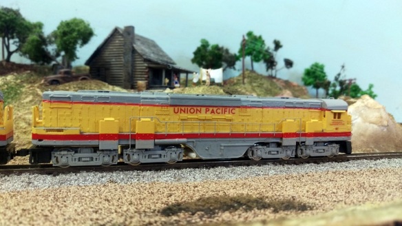
Later that evening C-855 no 60 received its handrails and ladders which made a dramatic change to the appearance of the loco.  All that’s left now is to finish painting the trucks and pilots and weather her up.

C-855 WIP 10

The C-855 is part of Alco’s ‘Century’ series of locomotives.  The C-855 is by far the largest and the only twin-engine locomotive. Two locomotives down the list is the C-630 and, as you can see, there’s a considerable difference.

C-855 WIP 11

Because the trucks are grouped in pairs linked by span bolsters they push the locomotive up, giving it towering dimensions compared to most other conventional two and three axle locomotives.

C-855 WIP 12

Once the C-855B unit arrives, which is due next week, it too will be painted by MRS and then all three will be weathered and ready for service.  These three are destined for a place in the UP engine sheds on the ‘Somewhere West‘ which you can find in the Layout Gallery or by clicking on the link.  I expect we’ll be getting lots of photos and videos of them in service and I also expect them to last a lot longer than the originals.

Joining Wire with Solder and Heat Shrink

I’ve been having one of those weeks when you pick up a job and have to put it right back down again, as life throws you another curve ball.  But not wanting to drop the bat in this weeks post, I will be making it nice and short and answering another question I’m often asked at shows and exhibitions.  What’s the best way to join wires together?

This question is normally asked in regards to fitting a DCC decoder into a non-DCC ready locomotive.  This is called hard wiring and normally requires connection of all the DCC decoder’s wires directly to the locomotive.  Often there are wires already in the locomotive that can be utilized and connected to.  And, as is often the case, there is very little room spare to make a connection.  The smallest, and best, method of joining the wires is to solder them together but this causes a problem.  At the point where the wires are soldered they are exposed, and could come into contact with the locomotive body or other wires and cause a short, or worse damage the decoder.

The answer is to use heat shrink.  This is readily available at most hobby shops and electrical stores, and there is endless supplies on the internet.  Heat shrink is a rubbery plastic tube that when heated shrinks to encase whatever is inside.  To show how I join wires together I did a quick demo.

Below is a standard piece of multi core hook up wire and a piece of heat shrink that is just a bit bigger than the wire.

Wire Joint With Heat Shrink 1

Using a pair of wire strips I strip back a about 4 of 5mm of the insulation and using a pair of snips cut off a piece of heat shrink slightly longer, maybe 10mm.

Wire Joint With Heat Shrink 2

The heat shrink is then slid over one wire end.  Normally you would have two wires 🙂

Wire Joint With Heat Shrink 3

Then using the soldering iron I tin the ends of the wires.  This means flooding the end of the wire with solder.  Depending on how powerful your soldering iron is will determine how long this takes, but typically it’s only about one to two seconds.  Hold the iron tip to one side of the wire and apply some solder to the other, as the heat runs through the wire it will melt the solder, causing it to flood into the wire.  You don’t need to add much, just enough to cover the individual strands.

Wire Joint With Heat Shrink 4

Then place the two tinned ends together, its easer if one is attached to something as you need one hand to hold the iron.

Wire Joint With Heat Shrink 5

Simply touching the iron on the two tinned ends for one or two seconds will cause the solder to flow together making a solid joint. This will now be stronger that the wire and will give the best electrical performance.  Note: make sure the heat shrink is not right next to the joint when you do this other wise it might react to any heat traveling down the wire and shrink where it is.

Wire Joint With Heat Shrink 6

Then, once cooled for a few seconds, slide the heat shrink over the joint.

Wire Joint With Heat Shrink 7

The bump in the heat shrink is simply where one of the wire ends was sticking out a bit.  If the heat shrink wont slide over you can squeeze the joint with a pair of pliers just enough to flatten it out.  Then its time to activate the heat shrink.  Normally this is done with a special heat gun but I simply use the tip of the soldering iron or a cigaret lighter if there is one handy.  Which there wasnt tonight!  The flame from the lighter will ensure it shrinks evenly but the iron tip will do the job although it looks a little rougher.

Wire Joint With Heat Shrink 8

And that is how I join wires.

Hopefully things will get back to normal this week and I can get back on track.  I will be at the Fordingbridge Model Railway Exhibition this coming weekend so I will hopefully bring you a review of the show and layouts in next weeks post.

Drawing an Alco C-855B for N Scale

Over the last few months I’ve been posting about my new locomotive project, the huge Alco C-855 built for the Union Pacific railroad.  This iconic engine, despite only being in service for 8 years out of North Platte in Nebraska, was part of the general pool of locomotives and ran in different consists with several varieties of Union Pacific power.  But it was delivered by Alco as a set of three; two C-855s and a C-855B cabless booster.  Together they produced 16,500 HP and were Alco’s answer to UP’s call for a loco to replace the ageing GTEL 8500 Gas Turbines.  In this post I’ll share with you my designs for the C-855B to complete the set.

Alco C-855B (Render)

The C-855B is basically identical to the C-855 with the only difference being the lack of a cab at the front end.  As you can see from the images below they are also the exact same length with all the same doors and features.

Alco C-855B Side View

Please note: the trucks are purely there as a representation, I’ve not drawn the proper truck assemblies yet. However I will be doing this so I can make a dummy chassis available soon.

Alco simply removed the cab section and added the same end equipment as the rear end.  Then they filled in the space with bodywork plate as you can see below.

Alco C-855 & C855B Front End

This means that the chassis is exactly the same, well almost.  Because there’s no cab a little bit more will need to be cut off the Con-Cor chassis as it gets wider where the turbine/U50 cab was.

This model is now available in both Shapeways FUD and FXD materials and can be found here.

The brass Additions for this locomotive are not the same as the C-855, the front handrails are different as well as the quantity of grab irons etc, so I’ve drawn a new sheet.  These will be available very shortly but if you wanted to pre-order them or both the C-855 and C-855B brass Additions it will give me a better idea of how many sheets I need to order later this week.  Please send me a message via the contact page or email me if you want to order any brass Additions.

The chassis and assembly instructions for both the C-855 and the C-855B are almost done and, once complete, I’ll be adding them to the site in a PDF format which you can download.  There are a few cuts that need to me made to the chassis in order to fit the shell and the exact dimensions will be included.

Together all three will look very impressive and I am greatly looking forward to seeing them all run.

Alco C-855 Triplents (Render)

My two C-855s are still at the painter’s but hopefully I’ll have some more pics to share with you soon.

In the meantime here are some photos from two customers who have already started painting theirs.

Brian Stewart has re-powered his chassis with an Atlas motor.

Alco C-855 1(Brian Stewart) Alco C-855 2(Brian Stewart).JPG Alco C-855 3(Brian Stewart).JPG Alco C-855 4(Brian Stewart).JPG

Mike Musick has primed his ready for the brass Additions and final paint.

Alco C-855 1(Mike Musick).JPG

If you have any work-in-progress photos or some of the finished locomotives running on your layout and you’d like to send them to me I’d be happy to add them to the site gallery.