Fixing bowing problems in 3D FUD printed models

Now the prints have arrived it’s time to clean them up and get them ready for painting. Actually I’ve had 3 versions of the log car printed so far with each being an improvement on the last.  The first was very short on detail, due to some modeling errors which have now all been fixed.  The second came out very well although I was unhappy with the deck planks all being exactly the same length; this caused the plank detail to disappear and the model looked too square and a little unrealistic.  The third and current version looks fantastic, although when I opened the box from Shapeways I could see there was a problem.  There was a bow in the main deck of the car.  I have had this before with other prints and it has resolved itself during the cleaning process. (please see my FAQs for more information on the cleaning process).

All the parts where put into a jar containing Goo Gone to remove the wax residue as normal.  I was hoping this might help soften the FUD material and fix the problem but unfortunately this time it increased it.  Here is the car after the cleaning process was complete.Log car with bow

So why does this happen?  Well the FUD material is printed along with a wax that supports the delicate parts as the print is developed layer by layer.  Once the print run is complete the parts are put into an oven to melt away the wax.  When the parts are removed and left to cool, one side will cool quicker than the other, and because this car is long and thin it will cause it to curl, very similar to the effect caused by heating and cooling a Bimetallic strip.

Although the Goo Gone softened the FUD material it was not enough to undo this effect, and leaving it to dry again caused the bow to increase.  However this can be removed from the model by using hot water.  Water at 150F (66°) will bring the model back to the temperature of the oven and the bend can be reshaped and as it cools it will hold the new shape.  For this log car, after making a cup of tea and letting the water in the kettle cool for a few minutes, I poured a small amount of the hot water over the middle of the car.  Almost at once it became softer and flexible, the bend straightened without any effort and I held the car in my fingers as it cooled and became ridged again.  In the photo below, the lower car is the one that had the bow in it.

Log car without bow
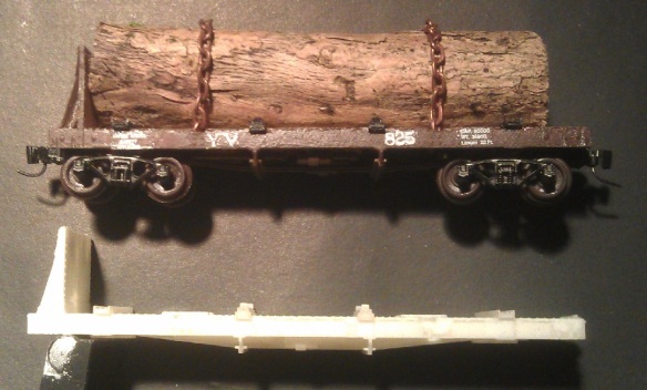
I had to be careful as it cooled not to let the effect make the car bow the other way, if this did happen I could simply pour on a bit more hot water.  I will now leave the car to totally dry overnight, checking that the bow does not come back.

In the next post we will look at painting and decaling the car.

Building a Yosemite Valley Railroad Log Train

Whilst spending some time traveling around Yosemite National park in CA, and the surrounding areas I came across the Merced River and then discovered the Yosemite Valley Railroad that used to run along its banks.  After buying a book and reading about the fantastic logging history on the railroad I became hooked and wanted to recreate it.

In particular it’s the logging operation which fascinated me and the cars the YV used to transport the huge cuts of Sugar Pine down from the High Sierras to their lumber mill.  The trees were forested by the YLCO (Yosemite Lumber Company) and the Yosemite Sugar Pine Lumber Co. high up in the wooded slopes but the railroad was hundreds of feet below in the gorge carved out by the river. To solve this problem the YV constructed steep incline railroads, one as steep as 78%, that worked by winching cars up and down the steep gorge sides. Although this system could be powered by a steam winch at the top of the incline the majority of the time it relied on the weight of the timber coming down the slope.  A fully loaded log car at the top of the slope was attached to a cable via a special bracket on one end of the car, the cable ran through the winch house and the other end of the cable was attached to an empty car at the bottom via the same special bracket.  As the loaded log was lowered down the incline the empty car was pulled up, and the winch house simply braked the cable.

What made the cars special, apart from the cable bracket, was they only had one bulkhead, at the other end from the bracket.  This bulkhead supported the logs as they were lowered down the incline; this along with the cars being only 36′ long and a light weight construction also made them perfect for running on the temporary railroads laid down by the YLCO and the Yosemite Sugar Pine Lumber Co. through the forests.  The same car could be used from the cutting site through to the lumber mill.

After doing some research I couldn’t find any ready-to-run models or kits for this car in N scale so rather than scratch building them I decided this would be a perfect project for 3D printing.

Using the dimensional information and the many photos from the YVRR book, I was able to draw an accurate 3D model of the car.

Yosemite Bulk Head Log Car 1

The 3D model contains all of the bolt heads, grab irons and detailed parts I could find in the drawings and photos.  The trucks, for now, are generic models based on Atlas trucks.

Yosemite Bulk Head Log Car 2

Even the underside has been detailed as accurately as I could.

Yosemite Bulk Head Log Car 3

Once complete it was time to think about how to make this into a practical N scale model.  A lot of the detail that has been drawn is unprintable at 1:160 scale, also the thickness of the sheet steel structure will be come too thin.  I spent some time enlarging details and thickening plates until it met the design requirements which Shapeways specify for their FUD material.  This also meant that the grab irons had to go, these are just too small to print and would look ridiculous if enlarged by the required amount.  I left the grab iron mounting plate detail on the car so brass wire grab irons could be added if required.

Yosemite Bulk Head Log Car (N Scale)4 Yosemite Bulk Head Log Car (N Scale)5 Details such as the diagonal angle irons which support the bulk head needed to be made into solid triangles, and the gaps between the deck planks needed to be enlarged otherwise they would disappear when the model is painted.

Yosemite Bulk Head Log Car (N Scale)6

The ends of the deck planks have also been made uneven to give a more realistic look to the car.

The car was now ready for a test print.  In the next post we will see how it comes out.

Improving a DD35

After completing the DD35 design one final improvement was needed to make it an accurate model; the corridor through the middle.  Bachmann’s very first model of the DD40AX was the only one to have a corridor that you could see through.  This was because there was not much of a chassis inside to get in the way.  All of the subsequent models had the opening in the shell but the large chassis with their twin motors blocked off any possibility of seeing through.

As we have already been cutting bits out of the chassis we used for the DD35, Bob Norris came up with the idea of cutting out a bit more.  Using the printed body as a guide, he cut the chassis down as far as the running board and removed the material.  Then he added two small “jumpers” at the top of the gap.  These were glued in place to strengthen the chassis.

2013-12-11 19.07.00 2013-12-11 19.07.13

When the shell was replaced the effect was fantastic, the DD35 now has the proper corridor though the middle.

2013-12-04 14.26.53

2013-11-26 18.30.42

Instructions on how to do this with your printed model can be found here.

Fitting and finishing a DD35 shell

Now the DD35 chassis has been completed and the shell has been printed it is time to put them together.  The prints arrived, along with some other parts I have been working on, in the usual big box from Shapeways.  They were all in plastic bags and covered in the waxy residue left over from the 3D printing process which gave them a slimy feeling.  Washing them in warm soapy water is the best way to remove the bulk of this residue but be careful not to have it too hot as there is a chance the plastic may warp.  I also put the larger pieces directly under the tap, this seemed to blast a lot of it off.  Once that was done the sliminess had gone from the parts which made them much nicer to handle.  The next step was to cut the handrails from inside the shell without damaging either, this with done with a sharp craft knife.  The blade ran along the inside of the shell and one by one the handrail posts popped off.  Here are all the parts laid out ready to be test fitted.

DD35 Shell & Chassis

The shell fitted perfectly sliding over the chassis and seated on the metal shelf.  The lip all round the bottom of the shell overlapped the shelf concealing the shelf on the chassis, just as the DD40AX shell had done.  There was a bit of tolerance allowing the shell to be positioned centrally on the chassis.  The fuel tank then clipped into place with a positive click.

New DD35 Shell

Comparing the DD35 next to a DD40AX, the walkways lined up perfectly. as did the height of the two shells.

New DD35 Shell & DD40AX

After test fitting the shell on the chassis it was time to prepare the shell for painting.  The parts, although having been cleaned in warm soapy water, still had a lot of the waxy residue in the grooves and details.  If this residue is left on the model no paint will take to the plastic so it needs to be totally removed.  A rubber cement solvent is a good way to do this but you have to be careful to find one that has no chemicals in it that will melt the FUD material.  One suitable product is Bestine, which contains Heptane.  Although this product cleans up FUD very well it is flammable and only seems to be available in the US.  I prefer to use a product called Goo Gone; this is also a US product but it is not flammable or toxic and can be ordered online and shipped just about anywhere. (It is also great for cleaning wheels).

All the parts where put into a jar containing Goo Gone and left for 24 hours.  A jar with a lid is best as the Goo Gone evaporates fast and you will want to keep the parts submerged for the process to work, and you can keep the Goo Gone in the jar to re-use the next time.  On removal the parts were washed again in warm soapy water and lightly scrubbed with an old toothbrush to wash away all the remnants of the waxy material that the Goo Gone lifted off the parts.  The parts will feel soft and flexible and they should begin to turn opaque with a yellow tint.  It is not recommended to leave them submerged any longer than 24 hours as they will continue to get softer and may start to deteriorate.  Once removed they will then need to be left to dry on paper towel for at least 24 hours.   After this they should have turned totally white and become rigid and hard once again.  The very last of the waxy residue will now have had a chemical reaction with the Goo Gone causing it to turn into powdery fuzz.  This can be scraped off with a dry toothbrush.  The main shell now looked like this.DD35 Clean Print 1

The fans still had some fuzz left in them which was a little harder to get out and took a little more persistent scrubbing with the dry toothbrush..  This was also the first time I could see all the detail and I noticed things like some missing bolt detail which was traced back to an error in the 3D model.DD35 Clean Print 2

DD35 Clean Print 3

There was also some rough patches on some of the doors which was also traced back to model errors.

DD35 Clean Print 4

DD35 Clean Print 5

Apart from the few small errors mentioned above, the first print was very good, and I was very impressed with the level of detail that came out. However, I have gone back to the original 3D drawing and ensured that future prints will not have these errors.

The shell was test fitted again just to ensure everything is okay, and it fitted just as well as before.

DD35 Clean Print 6

The shell and chassis was then handed back to Bob Norris for painting.  The shell was sprayed with UP Harbor Mist Gray and UP Armor Yellow paints from Badger paints.  The yellow was very thin and ended up being brush painted. In all this took five coats, but the detail showed up very well through the paint. The inside was also painted black to make the yellow color bolder.

DD35 First Paint

The next step, once the paint had dried, was to add the decals for the red lining, numbers and lettering.  Wet slide decals where used and these were then sealed with a coat of Testors Dullcoat (a clear matte overcoat) which stops the decals lifting off and removes any shininess from the decals and model.   The last step was to add the handrails which had also been sprayed with UP Harbor Mist Gray.  They were test fitted then super-glued into place.

2013-11-13 20.54.09

And here it is. A DD35 in N Scale, it runs perfectly and pulls like a DD35!  But as with all model railroads there is always more to do.  To weather it Bob added some grime and dirt to make the loco look like it had been working hard so he could run it with his GE U50.

EMD DD35-3

DD35 & U50

The time it took from receiving the first print from Shapeways to the finished product you see in the photo above was about a week. I have to thank Bob as his experience in painting and working on a different material whilst still achieving his usual high standard of finish meant we turned this project around a lot more quickly than if I had taken on this venture on my own. I’m very happy with the quality of the first model we’ve produced, and the next collaboration should be even better!

Shortening the Chassis of a Bachmann DD40AX

Having 3D printed the shell for an EMD DD35 I now have to alter the chassis of a Bachmann DD40AX so that the shell will fit onto it and give me a working locomotive. Actually, I can’t take the credit for the all the work done on this one, much was done by another modeller, Bob Norris, and the photos are courtesy of him.

DD40AX Side

There’s a lot of stuff on the circuit board, mostly used for directional lighting control.  The DCC decoder under the board is a standard Bachmann decoder.  We can’t shorten the chassis and keep the circuit board intact, so we decided to remove the entire circuit board and decoder…

DD40AX Top

this will later be replaced with a Digitrax chip…

DD40AX Circit Board

The Bachmann chassis is 24mm too long so the next problem is where to cut to shorten the chassis. We can’t lose length on either end because of the drive mechanism, but on the Bachmann chassis there are two motors, one next to each mechanism, so the only room left is in the middle of the chassis, between those motors. Each motor has an extra flywheel which fills this section but these can be removed, which would clear a space on the chassis of about 28mm.

DD40AX Motor Cut

Before you start shouting at the screen that taking 2 of the 4 flywheels out will make it less smooth, it didn’t. This is a cabless booster, it will be coupled to another loco, which will overcome any issues. So with that, let’s cut out 24mm. You can see the recess where the old fly wheels were.

DD40AX Center Cut Marks - 2

We marked the center of the chassis with the areas of metal to be removed. We also had to remove some material from the cab end, as the DD40AX was wider at this point and needs to be thinned to the same width as the shell body which will be dropped on top.

DD40AX Cab Cut Marks - 1 - Copy DD40AX Cab Cut Marks - 2 - CopyOnce the loco had been cut and re-assembled it was wired up for simple DC control, just to test, and it ran like a dream.

Reassembled

The joint between the two chassis halves was split with a plastic strip to separate the frame electrically.  In the DD40AX configuration the left and right sides of the chassis are separated by plastic washers which leave a gap of about 2mm.  To maintain the strength of the shortened chassis a plastic strip was added that filled this gap and bridged the joint. All the other faces where joined in a similar fashion, all glued together.

Reassembled Top

The view from the underside between the fuel tank mounts.

Reassembled Underside

Here you can see the cut down area where the cab was. We also cut down the top of this area to make room for the DCC chip, as there’s no longer space where it used to sit.

Reassembled Frount.15

And here it is with the DCC decoder reinstalled. The split front and back sections of the frame have also been joined by wires so as not to rely on the butted joint between the two halves.

Finished

This is how the shortened DD40AX chassis looks next to an unmodified original.

Finished With DD40AX

As you can see from the image above, there’s a lot taken out from the chassis. The result is the chassis for a working model of a DD35 locomotive, which is great as you can’t buy these anywhere else.

All in all I think a fantastic job, with thanks to Bob Norris. If you have any questions about shortening your own chassis to fit into your EMD DD35 locomotive shell  please feel free to get in contact.

Next post will cover finishing the model.