As promised, this week’s post will be nice and quick as today is a holiday, ‘Boxing Day’, here in the UK.
Thanks to Shapeways, who are rounding off the year with an ‘end of year sale’, I’m able to offer sale prices on some of my printed products. They are offering 20% off all Frosted Ultra Detail, Frosted Extreme Detail, and all Strong & Flexible Plastics through January 1st with code FAREWELL2016. You can use the links in the blog or shop on Shapeways site direct, just enter the code at the checkout.
Next week’s post will be the first for 2017 and I’ll be sharing with you the first of many new products.
For now that just leaves me to thank you for your continued support through this year and for 2017 I’d like to wish you all a very Happy New Year!
Following on from last week’s post about replacing the motor in a Con-Cor Turbine/U50/C-855 Chassis, which you can find here, I have a few updates to share with you.
This chassis has been around since 1973 and has undergone very little change. However there have been a few, and the more I work with them the more I find. One of my fellow modelers, Mr Mike Musick, who wrote the guest article about changing the wheels in these chassis, has discovered that the most recent version released under the Rail Baron label has a different motor cradle and the new Kato/Atlas motor will not fit. You can find Mike’s guest post about the wheel sets here.
The problem with the cradle is solvable by removing the part which clashes with the motor. Mike says ‘This plastic is hard and not trivial to work with, a Dremel with a small burr bit is about the only way to remove enough material.’ Below is Mike’s photo of a modified cradle.
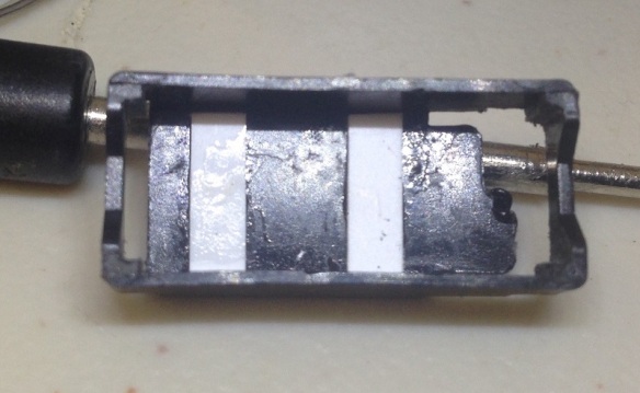
Mike also goes on to say ‘When removing the old motor, be sure to note the location of the “white stripe” on one side of one magnet. This indicates motor polarity, and the new motor should be oriented with the white stripe in the same relative position. This is especially important if it is not going to be modified for DCC;as with DCC if you get it backwards you simply swap the orange and gray wires.
The original motor in mine came with a 0.010″ shim in the motor cradle. So I swapped it out for an 0.020″ shim, which turned out to not be enough, it should be a total of 0.030″.’
The shim raises the motor as discussed in last week’s post, however too much will cause the gears to bind.
With the C-855 extended chassis Mike has also experimented with not gluing the cup gear extenders, shown below, into the cup gears. This ‘in Mike’s words’ ‘lets the adapter cup gears “float”, which turns them into sort of a constant-velocity joint and may also influence the noise by reducing gear pressure’.
These small changes can greatly affect the running of the locomotive by improving noise reduction and smoothness of the motor.
Bob’s three C-855s, from last week’s post, have now all had their motors swapped out for Kato Atlas Motors and I was able to catch them this weekend running through Solent Summit station. I haven’t added any sound to the video so you can hear, or rather not hear, the motors.
Next week’s post will be on Boxing Day here in the UK so it will be nice and short but for now I would like to wish everybody a Merry Christmas.
The Con-Cor Turbine and U50 chassis has been around for many years and has always been a solid runner. However, by modern standards, the motor in the chassis is rather noisy and draws a lot of current. In this post I’ll share with you how myself and Bob Norris replaced the motor to improve these issues.
The chassis, as pictured below, has a central motor powering two drive shafts which in turn power the two outer trucks. The inner pair is unpowered. The design has been used for the GE U50 model since 1973, which interestingly was first made for Con-Cor by Kato. This chassis was also used for the GE 4500 Gas Turbine model which was released in 1975.
And more recently it’s been used by me for the Alco C-855 as shown below, stretched and fitted with a DCC decoder. You can read more about the stretching of the chassis here or by searching this site for C-855.
The first three C-855s I made went to Bob Norris and the chassis have been running well but recently we have added sound decoders to them and this started giving us a few problems. Firstly the motors are fairly noisy and secondly they draw lots of current. When pulling a heavy train with the sound at full volume the sound decoders have been known to shut off and then start behaving erratically. Now I know the original three ordered by Union Pacific didn’t last long as they were prone to failure but that wasn’t the aim here!
So after doing some investigating we did a stall test on one of the motors and we discovered that the peak amperage can sometimes go over the maximum for the decoder by a fair amount. To find out what a stall test is and how to do it please see this post.
Below is a short video of a C-855, running light engine with the sound off so you can hear the motor whining. The clicking is the Digitrax DCC controller notching up and down.
To solve the issues a new motor was found for the chassis. Coincidently it is also made by Kato, although a much newer design. The Kato motor 420000 is advertised as a replacement motor for Atlas N Scale. We found them on eBay though the seller Soo-Much-Stuff.
The motor comes with no gears on the drive shafts which is ideal. Below you can see the new motor on the right and the old on the left.
The old motor, as shown below, sat in the middle of the raised area of the chassis and the gears ran inside larger diameter cup gears.
The chassis un-screws and separates easily allowing the motor, drive shaft and motor cradle to be removed.
The gears on the old motor (top in the photo below) need to be removed and fitted to the new motor. They are simply press fitted and can be removed by applying pressure behind the gear. Not too much pressure or you will spend ages looking for the gear on the other side of the layout, don’t ask me how I know this!
To fit them to the new motor the process is the same, just the other way around.
The gear needs to slide on far enough so the drive shaft is almost at the other side. Note, this was done for the C-855 extended chassis, the U50 and turbine chassis should be the same but it’s a good idea to check as you go. If the gear slides on too far it may not make good contact with the cup gear.
With the gears fitted the tabs can be bent up ready for soldering wires to. If you are doing this for a DC locomotive the tabs will need to be in the same positions as the motor you have just taken out.
The bottom tab pokes through the motor cradle.
Upon test fitting we discovered the motor was sightly smaller than the original which caused it to sit a bit low. To solve this a plastic shim was made to fit in the bottom of the cradle.
The cradle was then fitted back into the chassis ready for the motor.
As you can see below the gears now fit nicely into the cup gears. If the shim was too thick the cup gears would be lifting and this would cause noise and strain the motor.
The wires can now be added to the motor. There is a channel formed in the C-855 chassis extender on either side so you have a choice on where to run your wire.
The chassis is now fully reassembled and ready for testing.
Below is another short video showing how quietly the new motor runs.
With all three units converted to new motors the performance should be greatly improved and hopefully I will get some video of them running soon to share with you.
Thanks go to Bob for the photos and videos of the motor swap.
The new Shapeways order has now been shipped so next week I will start showing you some of the products I’ve been sharing over the last few weeks.
In this week’s post I have another 3D printed part to share with you. This time it’s a set of specially shaped bricks for a OO Scale signal box.
The Somerset & Dorset Railway’s terminus station at Bournemouth West had its own signal box, as most stations did. Sadly the station and signal box are no longer there but a group from the local area are recreating the terminus in OO Scale. I have already 3D printed an unusual chimney cap for the station building for them, which you can read about here.
The signal box was constructed with a brick base and wooden top which is common for the UK. However, just to be different, this one had a brick castellated feature around its lower windows. In the image below, captured from a video taken from a passing train, you can just make out the feature.
This has proven a very difficult building to find images for, so below is a photo of Carterhouse Junction signal box, take on the 5th April 1988 by Harry Gardner. It has a similar detail around the bricked up windows.
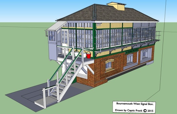
Luckily a fellow modeller, Frank, has painstakingly gathered enough information to 3D model the signal box and below are some screen shots from his 3D model.
Using measurements from Frank’s computer model the group will scratch build the signal box. But although Frank’s model has provided them with the information needed to do the scratch build it’s not a suitable file for 3D printing, and to make their lives a bit easier they have asked me to 3D print the brick feature. As you can see in the image above the bottom feature consists of two sloping sets of bricks. The top feature has one sloping brick and one alternate brick rotated by 90 degrees to form the brick castellations.
This was a fairly easy geometric shape to draw for 3D printing and as you can see below the two parts will come in strips, each measuring 51mm in length. Each brick, for 00 Scale, is 1mm wide so this can be 3D printed in Shapeways’ White Strong & Flexible material.
The WS&F will be ideal because the slightly grainy texture will help it look like brick, and this material also absorbs paints, leaving a matt finish, which again helps it to look like brick.
As with everything else I’ve ordered recently, these are still being printed but they are due to be shipped this week. So hopefully I’ll have them shortly and will be able to share them with you in next week’s post, along with the other parts.


You must be logged in to post a comment.