Getting Back on Track Part 2

Last week I shared with you my design for an N scale Re-Railer which can be added to your locomotives as a detail part.  You can find the post here.  This week I wanted to share with you how the 3D print came out and what it looks like on some of my locomotives.

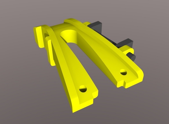
The design for the print, as pictured below, included the mounting bar and lugs so it could be fixed directly to the locomotive chassis, as was typical on a lot of switching locomotives.

Re-Railers Type 1-3

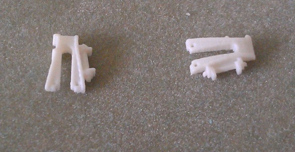
When the parts arrived they needed cleaning, as do all parts printed in Shapeways Frosted Ultra Detail material.  I did this by using my normal method of soaking the parts in Goo Gone for 24 hours, but before I did this I took some photos.  As shown below, even though the parts are transparent, the detail and shape is visible, although with an average phone camera getting the detail in focus is hard. Re-railer Type 1 Raw FUD 1Once removed from the Goo Gone I let the parts dry for a further 24 hours in which time they turned opaque.  They are still hard to photograph at this stage, not just because they are very small but the brilliant white reflects a lot of the light.

Re-Railers Type 1 - Cleaned

I brush painted the Re-Railers using a basic matt yellow acrylic paint.  To make sure I didn’t put on too much paint and fill all the detail I dipped the brush lightly into the paint then wiped most of it off on the side of the pot before painting the parts.

Yellow Paint

Again getting my camera to focus on such a small part created some issues as you can see below but the detail of the parts really stands out now they have been painted.

Re-Railers Type 1 - Painted

The next step was to fix them to some locomotives.  A good example of these in place on a real locomotive can be seen here and here on Canadian Pacific’s S-3 loco No. 6538.  I don’t have any S-3s on my roster but I do have various other locomotives that I want to super detail and I am starting with my Life Like Spokane, Portland and Seattle FA2s.

FA1 with Type 1 Rerailer

These models don’t have such a large fuel tank as the later FA2s so there is plenty of room for the Re-Railers to hang.  I used a gel super glue to fix it in place and I only glued it to the plastic shell and not to the models chassis, this enables me to remove the shell without damaging the Re-Railer.

FA1 with Type 1 Rerailer - Close Up

The trucks swing freely without knocking the Re-Railer and it doesn’t protrude past the shell so I can still put the locomotive in its original box.

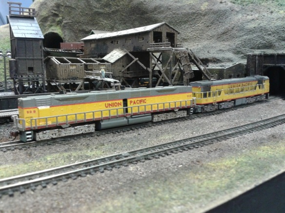
Re-Railers are more commonly found on switching locomotives and for this I often use my GP20, also made by Life Like.  The fuel tank on this locomotive doesn’t give as much room so I have mounted the Re-Railer under the shell at the center of the truck, as shown below.  This also enables the truck to swing freely as the Re-Railer is in line with the truck pivot where it moves the least.

GP20 With Re-Railer

This Re-Railer detail part is currently available in 3 different packs from my Shapeways shop or by clicking on the links below;

A set of 8

A set of 16

A set of 32

The GP20 locomotives also used a different style of Re-Railer which were carried on the side of the trucks; if you look closely at UP No. 475 pictured here you can see them.  I am also designing these truck mounted Re-Railers but that will be for another post.

Getting Back on Track

As well as the big 3D printed locomotive shells and parts, I often get asked for small parts and this week I wanted to share with you my design for my smallest yet.  I was asked by a fellow modeller if it would be possible to produce an N Scale Re-Railer to super detail his locomotives.

Re-Railers or Rerail Frogs as they are sometimes called come in all shapes and sizes, typically they are metal castings which are designed to be easy manhandled.  The type I will be looking at is a Y shape with a slot in middle which is designed to straddle the rail.  These are usually carried on locomotives, incase of rolling stock derailment, either on the side of the trucks or slung under the chassis.  They work by straddling the rail next to the derailed train car wheel, then the locomotive either pushes or pulls the car so that the derailed wheel runs up the Re-Railer and back onto the track.  Normally a pair of Re-Railers are used because when one wheel comes of so does the other, the Re-Railers are handed and are designed to work as a pair.

A good photograph of the exact Re-Railer I am modeling can be found here on the translation directory.

Modelling the Re-Railer was not the challenge with this project, that came with the actual size and making it printable at 1:160.  A real Re-Railer is barely 1 Meter (39″) long which in N scale is only 6.25mm (0.24″).  My first draft as shown below was an accurate model of the Re-Railer with some of the details over-sized such as the mounting lugs and flanges to make it printable.

Re-Railer Type 1 Draft 1

However even with the increased sizes the overall part was still unprintable.  The problem lay with the hole in the mounting lug.  In order to get enough material around the hole to make it printable the lugs became unrealistically large, and if the hole was made any smaller it would also not be printable.  To resolve this I also included the mounting bar and corresponding lugs as shown in the images below; these are normally part of the locomotive.

Re-Railer 1

Re-Railers 4

This solved two problems; firstly, by replacing the holes in the lugs with the bar the thickness of the lugs was no longer a problem, and secondly it would be easy to glue the part, once painted, directly to the underside of a locomotive chassis, as illustrated below on one of my DT6-6-2000 locomotives.

Re-Railer on Loco

However this design was also unprintable, but not by much.  The black mounting bar shown in the images above is technically a wire by the 3D printers definition of parts.  This means it has to be twice as thick in order to survive the post print process and to guarantee that it will arrive in one piece.  Where the bar protrudes out of the mounting lugs is okay because this is classified as a detail and is supported by the thickness of the lug. I didn’t want to increase the size of the mounting bar as again it would become too unrealistic so as a compromise I filled in half of the area between the bar and the main body of the Re-Railer as shown below.

Re-Railer Type 1Given the actual size of the part and that it hangs under the locomotive in shadow this will not be noticeable, especially if the raised part of the bar is painted a different color to the filled-in section.

The test print for the Re-Railer has now been completed and is due for delivery later this week.  In a later post I will share with you how it came out and what it looks like on real model.


Discovering the Possibilities of Etched Brass Part 3

Following on from last week’s post, where I showed you the first two sets in my new ‘Additions’ series of etched brass details, I promised to share with you some photos to demonstrate how effective the ‘Additions’ details really are. So in this week’s post I have some of the current work-in-progress photos for you.

So far we have only been working with the EMD DD35 Additions set; the weather here in the UK has been unusually fantastic so we’ve been making the most of it!

The DD35 set, pictured below, comprises of two long handrails for the sides and four corner handrails that need to be rolled into shape as I showed you in last week’s post.

DD35 Additions Set

DD35 Additions 1

DD35 Additions Parts

Below are some photos of a DD35 using the stock 3D printed handrails which will still be provided with the kits should you wish to use them and I think they work well when using the DD35 with a Con-Cor U50 as the stock handrail sizes match.

DD35 & U50 1

DD35 2

Having already cut out a set of Additions for a DD35 and having a new one under construction it was simply a matter of glueing them on.  They were a good fit using the same mounting locations on the side of the shell as the 3D printed rails and, as you can see below, they look very realistic.  They still need the final coat of paint to finish the model but I think the brass Additions really finish it off nicely.

EMD DD35 With Brass Etched Additions 1 EMD DD35 With Brass Etched Additions 3

EMD DD35 With Brass Etched Additions 5

Once complete I will have some more photos of this model to share with you as well as some of the Baldwin DT6-6-2000 with its brass Additions.

In the meantime, if you would like to purchase one of these brass Additions kits please drop me a message using the Contact page.

Discovering the Possibilities of Etched Brass Part 2

A few weeks ago I shared with you my designs for etched brass handrails and details to improve my Baldwin DT6-6-2000 and EMD DD35 locomotive shells.  These etched brass sets are the first in my ‘Additions’ series which will be available for all my locomotive shells.  Now that the first batch have arrived I wanted to share some of the results with you.

DT6-6-2000 Additions Set

DD35 Additions Set

The sets pictured above are etched from a sheet of 0.2mm or 8 thou brass and this has given me the ability to make handrails the correct actual scale size.  Although the brass is very thin I recommend using a very sharp, if not new blade in a craft knife to cut the parts out because pressure applied to remove them with a blunt blade will distort the parts.

The parts have small tabs which are only half thickness showing you where to cut them out, and making it easer to cut.  Depending on how close to the part you can make the cut it is likely there will be a small bur which can easily be removed by carefully filing the area with a flat needle file.  I found the best way to handle the parts was with a set of tweezers with a flat end.  Even between my fingers I could see the parts had the potential to bend out of shape. Below is one of each part from the DT6-6-2000 set.

DT6-6-2000 Additions Parts

The center leg of the end handrails, shown in the center above, is designed to be bent to form a dog leg as shown below. At the bend line the brass has again been etched to half thickness to mark the bend and make it easer to do.  I used my flat end tweezers to grip the brass at the bend line and pushed it over with my fingers.

DT6-6-2000 Addtions End Handrail

The sun visors for the DT6-6-2000 also have two stay bars that are designed to be bent back as shown below.  This again was done simply with the tweezers and there is an etched section at the bend point.

DT6-6-2000 Addtions Sun Visor

This can then be glued directly above the window as shown below on a different locomotive.

DT6-6-2000 Additions Sun Visor 2

These particular sets only have additional etched details on one side, for example the real DD35 handrail stanchions, as pictured below, are made from a folded plate made into a channel section.

EMD DD35 Handrail stanchion

To accurately model this detail I etched the middle of the stanchion to give a fluted effect as shown in the 3D rendered image and photos below.

DD35 Handrails Additions Close Up Render

DD35 Additions 1

DD35 Additions Close Up 1The small handrail sections shown above are for the ends of the DD35 and there is one for each corner.  Once they have been carefully cut out as shown below, again using the half thickness brass as a guide, they need to be shaped.

DD35 Additions Parts

To shape the end rails I rolled the brass handrail around the handle of a watch mender’s screwdriver handle which had the radius I was looking for.  As you can see from the results below the handrail section is now ready to be fixed to a DD35 Shell.

DD35 Additions End Rail 1 DD35 Additions End Rail 2

The ‘Additions’ series are designed to complement my range of 3D printed locomotive shells, enabling you to model in finer detail to suit your budget, and in a later post I’ll show you how effective the ‘Additions’ details really are.

In the meantime, if you would like to purchase one of these brass Additions kits please drop me a message using the Contact page.