In February of this year, I shared with you my design for a replacement set of Bachmann OO Chassis Fasteners & Washers; you can find the post here. Since then I’ve had some requests to do the same thing for the N Scale Bachman US locos. So in this week’s post, I’ll share with you my design for a replacement set.
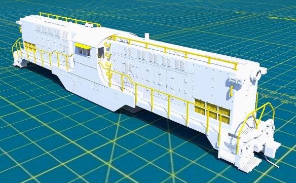
Unlike the OO set, Bachmann still has the N Scale version listed on their website as spare parts, but they’ve been out of stock for some time. The fasteners in question are used in the older locomotive designs from the 1980s. A typical example of this is Bachmann’s GP50 as shown below.
The chassis is a split frame design also used in several other locomotives, such as their GP40 and U36B models. It’s held together by the two chassis fasteners at the bottom corners of the chassis.
Viewed from the other side you can see the screw heads which pull the fasteners tight.
With the screws removed, the chassis separates and the trucks and motor will drop out. You can see the fasteners and a washer still in the upper chassis section.
The fasteners will push out and the washer will drop off.
Both the fastener and washer are made of plastic to electrically isolate the two chassis halves. The washer also acts as a spacer to correctly position the chassis halves.
As with the original OO versions, with time the type of plastic used hardens and becomes brittle, so when the screw is removed the cylinder part of the fastening breaks off of the rectangular sections as shown below.
Interestingly the OO and N Scale versions at first glance appear to be the same, but after doing some measuring I discovered the N Scale fastener is shorter and fatter. This means the N Sale washer also has a larger hole. Below you can see my OO fasteners and washers in white compared to an N Scale original one in black.
Using one from the GP50, it was easy to modify the existing OO version to create a new fastener for repairing N Scale Bachmann locomotives which have suffered from this part failure.
As with the OO set, the hole in the middle of the tube section will need to be cleaned out to remove the 3D print residue before the screw can be inserted. For the N Scale fasteners, I use a 0.8mm drill bit in a pin vice.
The inside of the tube has not been threaded for the metal screw so it’ll work as a self-tapping screw, cutting its own thread the first time it’s inserted. But if the tube is blocked, the excess material will create too much pressure and the tube may crack.
These replacement fasteners and washers can be used on a large variety of Bachmann N Scale locomotives and I’ve made them available in a set of 6 here and a set of 12 here. I thought it best to make the smaller set start at 6 so you have a few spares just in case something goes wrong.
These little fixes are ideal for 3D printing components, so if you have an idea for a part you’d like to see 3D printed please drop me a message, I’m always interested to hear what fellow modelers are working on. You can get in touch through the contact page.
Over the last two weeks, I’ve been working on the brass Additions to accompany the 3D printed parts of the HO Baldwin DT6-6-2000 and I’ve just finished them, so this week I’ll share with you how they look on their etched fret and where they go on the model.
The fret will be etched from 0.5mm (0.0196″) brass with a lot of the finer details reduced to 0.25mm (0.0098″). The 0.5mm was selected as it’ll make the handrails roughly 44mm wide at the scale of 1:1, which is ideal.
The main four handrails are in the top left of the fret. The shell has 3D printed mounting holes and locating marks to ensure these are installed at the right level. In the top right are the two end handrails which again fit into 3D printed holes in the shell.
Below the end handrails are the sun shades or visors which slide into sloping holes in the shell. Not all the DT6-6-2000 locomotives had these so I’ll offer both a shell with mounting holes and one without. Further down the etch are all the grab irons and the tiny windscreen wipers. Again, all of these parts fit into 3D printed holes in the shell. Some of the grab irons have tiny half-etched marks on the rear, allowing them to be bent at 90° in the right place.
Another part which will only be used on Pennsylvania Railroad versions are the antenna for the Pennsy train phone. Again, a different shell option will be offered with the slots in the roof for the antenna to drop into.
With all the parts listed so far, the shell will look like this with the exception of the grills, which I’ll come to later.
At the bottom of the etch fret are 16 parts that form the window boxes which were found on several locomotives, such as the Minneapolis, Northfield, and Southern Railway’s No 21, and later Elgin, Joliet, and Eastern Railway models.
The etched parts form the sill, roof, and sides and I’ve allowed space for glazing to be fitted, just like the other windows in the loco. Because the brass parts slide together, I’ve designed them so the inner two windows can be opened, just like the real loco.
The fixing for the brass window box is different, and the original window is removed, so this will be a fourth option that I’ll make available.
The last etch part I’d been planning was the grill mesh on the front of the nose. To get such a tight mesh it would’ve needed to be etched on a thinner sheet of brass.
A 0.2mm (0.0078″) sheet with half etching would’ve given this effect shown below.
Up til now I thought I’d solved the problem of the mesh design. However, upon doing some more research I found this really high-quality image of MN&S No 21 taken by Mike Roth on Flicker. You can see the original here.
Zooming in on the picture, which I haven’t been able to do this closely on all the old photos I have, I can now see it’s not a grill mesh at all but an actual radiator.
With my original N scale version, even though I thought it was a grill, I modeled it as a flat surface recessed into the shell. Once painted, it looked great. So I think the same thing will happen here and the etched mesh will be removed. My test print has the hole for the mesh but that can easily be filled with plastic card.
These etched frets are much bigger than my previous ones, not just because they are HO, but there’s more on them so they’ll be more expensive. The tools are the expensive part, and can’t be changed, that’s why I put the parts for different versions on one fret as it would cost too much to make several different ones. The price will be £10 GBP and I’ll be looking for some pre-orders to help cover the cost of getting the etch tool made. If you’d like to be one of those pre-orders please drop me an email at jamestrainparts@yahoo.co.uk or get in touch via the contacts page.
Once I get the first set I can test fit all the parts, make any adjustments to the 3D model, and then make all the different versions available. The brass etches for the Baldwin RT-624 will be different because the handrails and end rails are a different shape. But I’ll come to that later when I convert the DT6-6-2000 3D model into the RT-624.
As the HO Baldwin DT6-6-2000 project moves to the end of the testing phase, one of the key features I designed into the locomotive still needed testing: the powered Kadee couplings. I think these will be a great addition as this locomotive spent most of its life moving freight around yards, so this week I’ll share with you how it went.
For those of you who’ve been following the design and build of this locomotive from the start, you may remember I decided to use Preci Models DCC auto uncoupler system to automate the Kadee couplings. You can read about that in my earlier post here.
Because I’m designing this locomotive shell from scratch I had the option to mount the Preci Models motor in a more convenient place rather than simply fixing it to the back of the coupler as shown below.
The tiny motor fitted perfectly into the shell, with the brass spindle protruding out just behind the Kadee coupler. It’s very close to the shell mounting hole, but that’s the great thing about designing the shell as a 3D computer model; I knew it would fit.
The couplings I’m using are Kadee #148. These are medium metal couplers with the Whisker®. The Whisker® is the tiny wire you can see either side of the actual coupling arm which keeps the coupling centered in its box.
To make these work with the Preci Models motor, I needed to cut a slot in the rear of the box. As the plastic is fairly soft this was easily done with a new blade in a craft knife.
The string, which is supplied with the Preci Models motor kit, can be laid through the coupling box. The string needs to be parallel with the coupling arm otherwise it will put more effort into pulling the coupling to the side rather than opening the coupling knuckle. The string also needs to run free from any obstruction inside the box; it will be above the Whisker® as shown below.
With the box lid fitted you can see how the string passes through.
There are different ways to connect the string to the knuckle but I like to use a drop of superglue. To do this I put a drop of superglue on a piece of card, use a small toothpick to place it on the right spot, then lay the string in the glue. I also use a spray actuator to instantly set the superglue. It’s important to note the spring on the side of the coupling; you must not get any glue in this or the coupling won’t work.
The coupling can now be tested. By simply holding the coupling box between my fingers I can pull the string down and the knuckle should open.
There should be no resistance, other than the small spring on the side, which should cause the knuckle to close with a little snap when the string is released.
The coupling can now be screwed to the shell. Of course, I would recommend painting the shell before fixing the couplings as you don’t want to get paint on any of the moving coupling parts.
The string is pulled by the rotating motion of the motor and it’s important to keep the string as straight as possible, so in the picture below you can see I’ve wrapped the string around the motor spindle in an anti-clockwise direction. This way the string will come off the spindle at the top and be in the right place. To keep the string in place it’s actually tied onto the spindle, adjusted to the right tension, then fixed in place with another drop of superglue. Again, I do this with a small toothpick to avoid getting any between the spindle and the motor.
Next, we need to power the motor. It’s worth pointing out here that this system works on the principle that the motor spins as much as it can, which may only be half a turn, then stalls until the power is turned off and the spring in the coupling pulls it back. If the motor is left powered on for more than 5 to 10 seconds it will overheat. Also, if the motor is powered directly from the decoder or track, it will again overheat and probably burn out. So the Preci Models motor kit has two 68 Ohm 0.5w resistors, one for each motor, which needs to be included in the wiring to limit the power running into the motor.
The motor needs a minimum of 150mA of current to work and not all decoders can provide this from their function cables. It should say on the decoder documentation. There are options for this in the Preci Models motor kit instructions but this locomotive will eventually be fitted with an ESU LokSound decoder that can handle this. For this test, I have a basic ESU LokPilot which also has the required power output. First I connected the red motor wire to the Blue DCC chip common and the black to the purple DCC chip function wire.
As the motor is a DC motor and the DCC decoder outputs +DC from the blue wire and -DC from the function wires, the motor spun clockwise when wired like this, and that’s not what I wanted. So I swapped the red and black wires over and the motor now spins in an anti-clockwise direction.
With the chassis sat on my programming track and the DCC decoder plugged in I was able to test the coupler, and it worked well. With the function wire activated, the motor span and the knuckle opened all the way as shown below.
And when the function was turned off it sprang back.
Here’s a very quick video of it working.
Once I was happy it was working properly I trimmed the excess string off the motor.
The last test was to fit the shell to the chassis and try it in situ. The string on the knuckle is hardly noticeable, and I think once the shell is painted you won’t be able to see it at all.
I don’t have a long enough length of HO track on my modeling bench to do a full action test but I was able to simulate it using another loco in this video below. The SP&S Geep looks high on the right because there was no track under the rear truck and I was holding it up! But as you can see the powered coupling on the DT6-6-2000 works perfectly.
I won’t install the coupling at the other end yet, as I want to paint the shell first, but I’m very happy with how the automatic Kadee uncoupler works and I think it’ll be very valuable on shunting operations.
The very last test for this shell is fitting the etched brass parts and I’m very close to having them all drawn; it’s taken a little longer than expected, but I want to get it right and the better the design of the etch sheet the more parts I can get on to it, which in turn brings the cost down. Hopefully next week I can share that with you as well.


 A 0.2mm (0.0078″) sheet with half etching would’ve given this effect shown below.

 With my original N scale version, even though I thought it was a grill, I modeled it as a flat surface recessed into the shell. Once painted, it looked great. So I think the same thing will happen here and the etched mesh will be removed. My test print has the hole for the mesh but that can easily be filled with plastic card.


 There should be no resistance, other than the small spring on the side, which should cause the knuckle to close with a little snap when the string is released.


You must be logged in to post a comment.