As you may have read in my previous posts I am currently building a pair of modules to form part of the Gosport American Model Railroad Group’s N Scale Layout. In this post I will share with you a quick and cheap method to make some talus, boulders and general rock debris.
You can buy bags of talus form companies like Woodland Scenics in a variety of sizes but sometimes having a larger variety can be useful. If, like me, you have cast your own rocks from rock molds (you can read more about doing this here) then it’s likely you have lots of bits of plaster left over. I tend to fill up my rubber rock molds and this causes plaster to flow over the flat rubber and mold sides. When I break out the rocks these pieces break off and I collect them in a tray.
Depending on what you want to use your talus or rock debris for will depend on how you color them, but for me I want to simulate fallen rock into my canyon and rock that has been washed down the river in the winter floods. From reference materiel I have noticed that there is often less difference in the color range of the talus than in the actual rock faces. This might be because only certain parts of the rock face are crumbling due to the different rock composition so only the softer rock will be in the bottom of the canyon. Given that my dominant rock colors in the canyon are yellow ocher and burnt umber my talus will be a blend of these two colors. You can read about my rock painting process here.
So here is my recipe for rock soup! I start with a tray of plaster bits and crunch them up with my hands until they are roughly the right size. Then I pour on a bit of burnt umber that has been mixed with water at a ratio of 1 part pigment to 16 parts water. I give the mixture a stir to move the parts around.
The pigment soaks right into the dry plaster parts as you can see in the above photo. Because I didn’t add a lot of pigment it only soaked into certain faces in a similar way to the leopard spotting I used on my rocks. Next I add yellow ocher mixed at the same ratio 1 part pigment to 16 parts water. This time I added a lot more pigment so all the bits get a good soaking, hence the term ‘rock soup’.
The rocks in the tray are stirred and shaken up so all surfaces get a good coating and the mixture is left for an hour or so to ensure the rocks get thoroughly saturated. That way if they are chipped or broken they won’t show through brilliant white. Once I am happy with the amount of saturation I drain off any excess liquid and leave the rock parts to dry. This may take a day or so and it is a good idea to give them a stir now and again which will bring the wetter bits to the surface helping them to dry faster. This processes will also work on Woodland Scenics’ talus as you can see below. The lower tray is all the plaster debris and is a lighter color because it is a more porous material than the Woodland Scenics’ talus. However the two will mix together well.
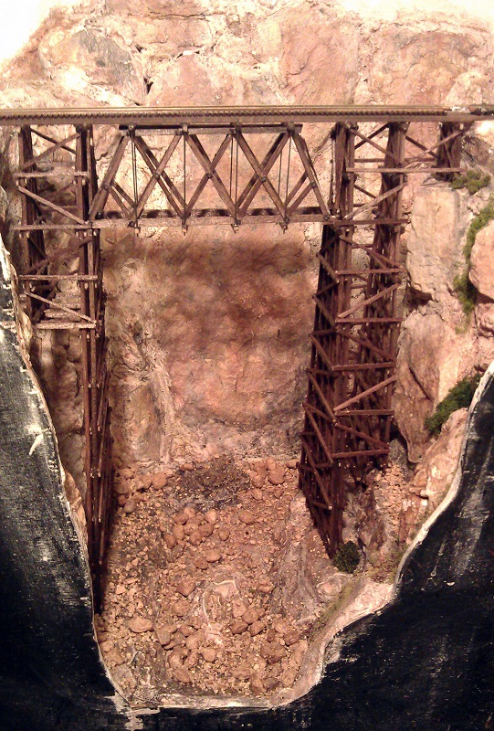
The area I am going to be using this on is the bottom of my canyon which you can see in the pictures below.
The river bed has been painted and is ready for some debris. I start by dropping some of the mixture down the rock faces to see where it lands, also I add clumps in areas that would have caught rocks when the water was flowing at full strength in the winter months. All the modules on the GAMRG’s layout are set in late summer so the water level will be low.
Next I use a watered down PVA glue in a spray or mister. Again Woodland Scenics sell the right glue for this called Scenic Cement but you can make your own. They also sell the spray bottle but I tend to use a basic one with a removable nozzle purchased from a garden center designed for misting plants. It is a good idea to have a bowl of water close by so you can put the nozzle in to soak between spraying as it will start to clog up. Because the mister gently soaks the areas it doesn’t move the rocks about. I tend to place the talus is several stages giving the area a good soaking of scenic cement between each layer.
As you can see below I do mean a good soaking. The talus is heavier than scenic scatter material and you don’t want it coming off the layout, especially a modular one that will get bumped around between shows.
You don’t have to wait for the first layer to dry before adding the next, in fact it is best not to as the new layer will sink into the wet glue adding to the strength.
Once you are happy with the amount and overall look give the whole area another good soak with glue and leave it overnight to dry. Don’t be tempted to touch it until it’s dry as the talus will be very easy to dislodge until the glue has totally set.
Once all the glue has dried it will become clear and leave you with a solid scene that you can add water to or simply leave as is.
I still need to add some more vegetation at the river edge and add the water itself which I will share with you in another post.
This coming weekend, the 3rd and 4 th of October 2015 I will be at the Fareham RailEX model railway show with part of the GAMRG’s N Scale layout. The exhibition will be at the Fareham Leisure Centre, Park Ln, Fareham, Hampshire PO16 7JU, UK and you can read more about the show here.
My new modules that I am working on will not be in this show as they still need a bit of work but it would still be nice to see if you are in the area.
Over the years I have tried all sorts of methods to ballast track. Some have been very time-consuming and some have just looked rubbish. In this post I will share with you a method I have found to be fairly quick and easy and also gives good results.
Ballasting track is a key part of building a model railroad or railway. Not only is it necessary for making the track-work look right but, just like the real thing, the ballast holds the track permanently in place.
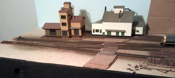
The current layout which I’m working on is an N Scale modular layout and forms part of the Gosport American Model Railroad Groups ever-growing layout. This particular module, New Mills, is a small country halt next to a group set of factories. The halt is used mostly by the factory workers and small town nearby. Most of the trains pass without stopping so rather than platforms the tracks outside the halt have been boarded over so passengers can access to the local passenger cars via their steps. Below is a photo of the left hand end of the module The main line enters on the left nearest to the front. It splits into two tracks that pass the station depot and then rejoin each other before leaving from the right hand end. The third line with the end of a GP38 sat on it is the entrance to the factory sidings.
Before I even think about ballasting track I always do lots of running on the layout to make sure everything works okay. The track is glued down onto a cork road bed which in turn is glued to the module top. The cork is important for a few reasons which I will cover in a bit. In the picture above you may have noticed that the track has been weathered. This is not a necessity but it adds the realism I like to see; railroads are not a clean place.
I have several methods of weathering track. First there is the spray paint method. This can be done with an airbrush or aerosol can. For the bulk of this module I used a grimy brown color aerosol. Before spraying I removed everything from the module and simply sprayed along the tracks. Then I quickly wiped the rail heads with a cloth to remove the paint. Once the paint had dried I also ran over the rail heads with a track rubber to totally remove any paint residue. Since doing that I have also added a few more bits of track but as I don’t want to risk spraying other stuff now fixed to the module I used a brown wash to weather the rails.
Making a wash from paints is fairly easy but I find this the quickest. Once the pot is shaken up the wash inside simply paints on. I tend to roughly brush over the ties and rails then brush again with no wash on the brush. This removes any excess wash and gives a mixed finish. As before I wipe the rail heads over with a cloth. Once you start to weather your track any new sections stand out as you can see in the photo below.
Once all the track is weathered and had a chance to dry I tested it by running a few trains. Then it’s time to add some ballast. Ballast comes in all sizes and colors. For our group modules we stick to the same make and colour for continuity which is Woodland Scenic Fine Gray ballast.
On the real railroad the track is laid on top of a deep bed of ballast, then more is poured on top and packed or tamped down tightly around the ties. Because the track is on a bed of ballast it is easy for the track gang to raise or lower the track to ensure smoothness as well as adding any special enhancements such as super elevations on corners. Also this means the track is raised off the floor and the ballast acts as a natural soak away to stop water from flooding the tracks. Given most track ties were timber this was a good thing.
On the model railroad adding a bed of ballast is not very practical so we use a layer of cork. Then when the ballast is poured on and covers the cork it will look like a nice deep bed and form the correct shoulder or slope on either side.
To start with I simply pour the ballast on in the right area trying to gauge the right amount. Then using my finger I run it along the center of the tracks spreading the ballast evenly around.
Then to get the right finish I use a small paint brush to carefully move the blast around. This works for most of it but there will always be the odd bit that gets in the wrong place.
The main area to worry about is the inside of the rail as this needs to be kept clear for the wheel flanges to run in. I find the best tool for cleaning this is a small watchmakers screwdriver which can be run along the inside of the rails and knocks off any stray ballast.
The area in the photo above is a little thick with ballast by intention. Normally ballast is leveled off just below the tops of the ties and the excess is moved down the line. However at that particular section the track is flanked at both ends by a boarded walkway and roadway so the excess ballast tends to get left there and forms a ridge down the center of the track. On the other side of the roadway the ballast starts to get a bit thinner as the track crew have more room to spread out the ballast.
When it comes to turnouts it’s okay to add ballasts around the rails but the gaps between the check rails and inside the frog (the V shape in the middle) must be kept clear. Again the small screwdriver is ideal for this. It is also important to keep the moving areas free so keep moving the turnout blades thoughout the process.
Once the ballast is in the right place I use an old freight car with big flanges as a tester. I run it up and down to make sure there is no ballasts where it should not be. I also change the turnouts. Note: if you have solenoid operated turnouts the sudden bang will dislodge the ballasts and can also bounce it into areas you don’t want it. Although this can be useful for removing it if you have got some in the turnout blades.
Once all the turnouts can be thrown, manually, and the test car runs up and down, it’s time to stick the ballast down. For this I’m using a product from Noch that was recommended to me.
I have used other ballast glues and made my own in the past but this product works better than any of them. The dispensing nozzle allows you to carefully and accurately drip or drizzle the glue where you need it and it doesn’t cause any lift in the ballast. By ‘lift’ mean the ballast raising up onto liquid glue that has not soaked into the ballast. It does not bubble or flow along the ballast causing washouts; it simply runs in. In the picture below I started in the center of the track from the left, and although I was a little heavy-handed the ballast glue still soaked in anway.
I then worked around the tracks covering all the ballast.
Before the glue has a chance to dry I did one more test with an old freight car. This is why I use an old freight car as you get glue on the wheels. Then I left it overnight to set fully. The next day all the ballast was dry and any surplus could be picked up with a vacuum cleaner. Because the rail heads might have been covered in the glue I used the track rubber again to brighten them all up so I could do a proper test with a loco.
The next step, which I still have to do, is to weather the ballast. Out on the main line the ballast would be fairly clean but at the ends of a station area like this there would be coal, oil, grease and diesel spills where locomotives would have been stood.
You may also be wondering why I haven’t ballasted the track in the industrial area? Well, this track work is under the obligation of the factory owner to maintain, not the railroad, and the ballast will be lower and dirtier, not to mention full of weeds at the ends of the tracks. To do this I need to mix up some ballast with other products and I will share that with you in a later post.
The German firm Minitrix, now owned by Markin, used to produce a range of US and UK steamers as well as their native German locomotives. Most of these early models date back to the 1970s and are still running strong. However there are a few parts that are prone to breaking and in this post I will share with you how to repair the crank pin on a Britannia class locomotive.
Minitrix used the same chassis or a variation of the chassis on a variety of locomotives. In the US it was the 4-6-2 K4 and 2-10-0 Decopod. In the UK it was the 4-6-2 7P Britannia, 4-6-2 A3, 4-6-2 A4 & 2-10-0 9F class engines. These all had metal side rods, drive rods and eccentric cranks but the eccentric pin that holds it all together is plastic. And it’s this part that has been known to break. If you look at the model in the picture below I have circled the crank pin in red. The side rod connects all three driving wheels together and is the nearest to the wheel. The connecting rod or main rod is fixed to the center wheel and runs into the cylinder. The crank pin holds the connecting road and side rod to the center wheel. The eccentric rod connects to the cranked end of the pin and drives the valve gear in the cylinder.
The crank pin is designed so that the side rod and connecting rod can easily rotate without binding on the pin but are also held in place. So you can see how this works I have modeled the crank pins below. The square shaft on the end of the pin fits into the wheel. Because it’s square this will ensure it will rotate with the wheel. The side rod and connecting rod fit over the round section and are held in place by the wheel and cranked top. The holes in the side and connecting rods are larger than the pin to allow free moment.
What normally happens is the metal rod assembly becomes jammed and the weakest point is the plastic crank pin. The pin breaks where the round section meets the square section and falls out. The connecting rod then flails about and can become bent. With this 4-6-2 that is exactly what has happened, although luckily the connecting rod wasn’t bent.
So to fix this engine the first thing needed is a new crank pin. Spare parts for these engines ran out years ago so my next option is to 3D print one. I printed some using the 3D model above in Shapeways Frosted Extreme Detail material. It will also print in their Frosted Ultra Detail material.
Next the old square section on the crank pin needs to be removed. For this I used a small drill in a pin vice as you can see below. I selected a drill that was a bit smaller than the pin. Once I had drilled through the pin the remaining materiel was so thin and weak it pulled out with a pair or tweezers. You can see the remains of the pin under the new one.
In the image below you can see the old and new parts next to each other. The old crank pin is connected to the eccentric rod by a metal pin which has a flared end and cannot easily be removed. One option is to cut off the old plastic crank and un-flare the end of pin hoping to fit it into the new one. However that is very hard to do.
To make this job easier I did cut off the old plastic crank but I did not un-flare the pin. Instead, using a very sharp craft knife, I cut through the loop on the end of the new crank pin. This then forms a C shape although the two ends still touch. Carefully spreading the new C shape I was able to push it over the metal pin as you can see below.
The connecting road and eccentric rod were then refitted to the loco.
The new crank pin simply push-fits into the driving wheel, ensuring it passes through the hole in the connection and side rods.
It is important to make sure the crank pin is pointing in the right direction, which is towards the center of the wheel.
The next part is to test the the new assembly and what could be better than running it on a layout. Below is short video of the engine running demonstrating that the new crank pin works perfectly.
The rocking motion is caused by the traction tires as the loco is supposed to be moving.
The last thing to do is to add some silver paint to the new crank pin to help blend it in. It’s best to put on as little as possible as you don’t want to paint the parts together or cause a bind.
A pack of four replacement crank pins is available from Shapeways here.
Alternatively if you would like this repair made to your locomotive for you, you can contact me though the contact page or directly at jamestrainparts@yahoo.co.uk and we can arrange to get it done.
This week’s post will be a bit different in that it won’t be about model trains, it’s not even about trains! But it is about steam, lots and lots of steam, because I’ve been to the 2015 Great Dorset Steam Fair and for those of you who have never been to or even heard of this event I thought I would share some of it with you.
The UK has a proud history of mechanical machinery and throughout the year steam rallies and heritage shows can be found up and down the country with all sorts of vehicles and machinery on display. But the Great Dorset Steam Fair is the largest and is also now known as the ‘The National Heritage Show’. The event is quite literally huge and covers and area of 600 acres. It is open to the public for five days; many of the exhibitors stay for seven or eight. On average the show draws in 200,000 visitors with tens of thousands camping on site to enjoy the night life. This year’s show was the 47th and was also the biggest I have been to so far. The show is the largest of its type in Europe.
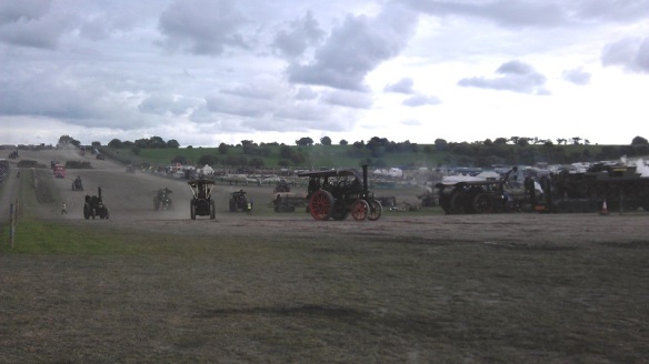
What makes the event so special is the machinery is not just on display; it is working and doing what it was made for. There are 5 main display rings or arenas and the largest is the heavy haulage ring. In here you won’t find vehicles parked up with judges walking up and down but a cacophony of sound, color and smoke as heavy loads are dragged up and down the hills behind traction engines, vintage lorries & steam rollers.
This year I was only at the show for one day and it’s not possible to get round it all and see everything in that time but I did get lots of photos and some videos for you. These were all taken on my ageing mobile phone so the sound quality is a little rough but it gives you an idea. It was also an overcast day but that didn’t stop the crowds.
So what does all this sound and look like? Well below is video taken alongside the heavy haulage ring with some of the traction engines running past.
The heavy haulage ring, referred to by the drivers as the ‘Play Pen’, is in the shape of a dog bone to allow easy turning at each end. All the movement is in an anticlockwise direction. The lowest part is in the center and at either end is a hill which makes the engines work hard and pleases everybody. The nearest hill to the center of the show is smaller and is where all the trailers and loads are picked up or parked. The far end is the largest hill and requires a lot of skill to get the big loads up it.
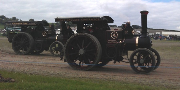
The main vehicles in the heavy haulage ring are traction engines and these come in all shapes and sizes.
The traction engine or road locomotive above is a McLaren called “Gigantic” built in 1911. It was designed as a heavy haulage tractor, and has been put back to its World War 1 livery when it would have been used to pull large guns and supplies to the front line. They were called ‘road locomotives’ as a ‘locomotive’ was term used to describe a railway engine.
Alongside the ring, traction engines wait for their turn, below ‘Britannia’ sits in the sun.
The engine below is great example of an agricultural (general purpose) engine which has been worked hard.
Sitting by the ring for any period of time you will see a huge variety of machinery pass by.
Throughout the day there are different demonstrations in the ring, below are some photos of an exhibition of cavalry officers on horseback reenacting charges; they were attacking cabbages!
As the ring is so big the action carried on behind the horses and below is a video of some of the traction engines shifting the biggest load around the lower part of the ring before they tackled the big hill. Note, the traction engines were doing all the work, the truck was there for emergency brakes.
All sorts of different loads were available and throughout the day different engines pulled different loads.
Below is a team of engines pulling a huge transformer up the big hill, and down again. The engine on the back is normally used as a braking engine.
The team rested at the top before making the descent.
All over the site there are traction engines, all singing with steam.
Here is a video of one just passing by.
The engine below, ‘Leviathan’, is a portable engine used to produce power only as it could not move by itself. This would have been towed to a site and used to drive anything from wood cutters to thrashing machines out in the fields.
As well as traction engines there were also steam wagons and lorries. Foden was one of the major manufactures of steam wagons and lorries and below are some great examples.
The steam lorry below was designed as a heavy hauler with its twin axels for added traction.
Sentinel was another big manufacturer and below are some perfect examples.
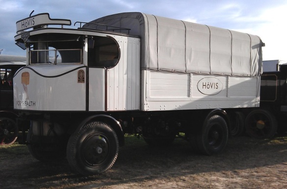
The steam lorries were, for their time, very fast and in the video below you can see the ‘Hovis’ Sentinel steam lorry charging through the heavy haulage ring on its way up the big hill.
What helps make the lorries so fast is they are chain driven, not directly geared like the traction engines. Below you can see the chain casing on the rear axle with the chain just protruding out the bottom.
The steam wagon below has also been returned to its World War 1 livery.
Here is another video of steam lorries doing their thing in the heavy haulage ring.
And where there are lorries, there are cars. Steam cars, that is.
And here is a video of them charging round the area. For a fee of £5 you could get a ride in one with all proceeds going to charity.
The vehicle below is a diesel-powered World War 1 gun tractor built in the US for the British Army.
We also had a World War 1 tank crawling around the arena.
It was a fairly slow mover as you can see in the video below; it actually crept up on me as I was filming by the gate to the arena.
As well as all the steam there was also hundreds of heritage cars, lorries, buses and motorbikes on show around the site. My personal favorite are the Scammell trucks. Below is a Scammell Constructor named ‘Viking’.
Here is a Scammell Highwayman.
And my favorite, the Scammell Explorer. It’s a World War 2 tank recovery truck.
And if you happen to have one lurking around your barn that you don’t want, please let me know!
And of course the big Scammells got their chance to play in the heavy haulage ring.
The Scammell Explorers make the best sound and you can hear them as they enter the ring in this video.
Once they had done a few laps and calmed down they started on the big loads.
Old Glory magazine had a big marquee at the show with several engines under repair. I think the one below need a bit of work but I reckon we will see it steaming again one day.
Another type of traction engine comes with a crane. This made them very versatile and elsewhere on the site they were in use moving logs, barrels and machinery.
Steam rollers were also a big part of the show and there was a whole area dedicated to them although I didn’t get time to visit that part of the show. They were actually being used to create the new roads through the site.
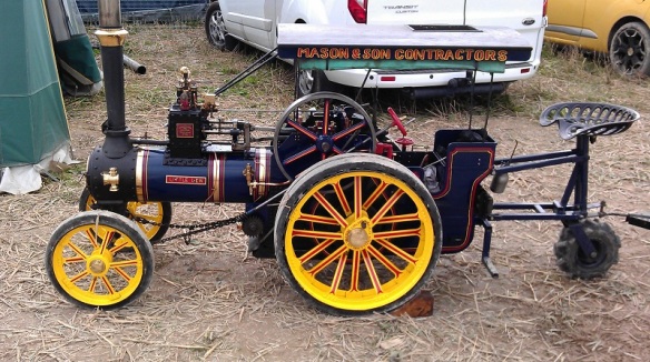
Alongside the heavy haulage ring was a sectioned-off strip given to the miniature engines and these realy do come in all shapes and sizes. There was a field full of them; here are a few.
Below we have miniature traction engine ‘Little Lew’
In the photo below we have a big miniature ‘Lady Of the Lake’ and small full-size running next to each other.
Miniature (if you can call it that!) traction engine ‘Galanthus’.
Miniature traction engine ‘Black Pearl’.
Miniature traction engine ‘Bagpuss’.
This one was tiny!
And this one is my friend’s miniature traction engine, ‘Emily’.
She has just been rebuilt and I was lucky enough to have a ride around the ring with her.
As well as working machinery there are also fields of auto jumble where you can buy all sorts of things. Spare engine, anybody?!
At intervals around the show were the fairground organs and a lot of them were steam-powered or at least driven by a traction engine.
In one of the big fields to the side of the show, the ploughing engines could be found working hard.
The ploughing engine is almost the same as a traction engine but it has a longer boiler to make way for the large winding drum underneath. Although you can’t see it at the top of the field there is another ploughing engine. The cable from both engines is attached to a plough and they take it in turns to pull the plough across the field. To speed up the operation the plough is often double-facing. This means you don’t have to turn it arround. In the image below you can see the plough with three people sat on one side of it to weigh it down, the engine on the left is pulling. Once it gets to the end the people will sit on the other side and it will swing over like a seesaw. The engine which was pulling will give two blasts on the whistle and the other engine will start to pull.
Below is a video showing the ploughing engines working and in the middle of the video you can see the cable winding onto the drum.
And not to be left out here are two miniature ploughing engines doing the same thing.
Elsewhere on the site the showman’s engines are hard at work powering the fairground, and attractions. And when I say powering, I don’t mean with mechanical power but electricity. The showman’s engines are again similar to traction engines but they have a full roof and an extra section on the front that overhangs the smoke box door. On this over hang is positioned an electric generator, sometimes the bigger ones have two. The engine below, ‘Lion’, was powering a ride behind it; you can see the wires hanging down from the left hand side of the generator.
On the side of the generator mount are two gauges measuring the voltage and current draw; ‘Lion’ was producing 110 volts and 200 amps. Each time the ride started up the amps shot up to almost 400 amps and ‘Lion’ gave a satisfying bark as the governer kicked in to maintain the constant speed.
Most of the organs and stage shows had one or several showman’s engines providing power. Below is ‘Cary On’ with the ‘Gavioli’ Organ and stage show.
Showman’s engine ‘The Masterpiece’ and living van.
Showman’s engine ‘Evening Star’.
Showman’s engine ‘His Lordship’.
But the biggest concentration of showman’s engines is the line up powering the big fairground.
I didn’t count them but on one side there must be 50 showman’s engines of all sizes.
Here is showman’s engine ‘John Murphy’. You can see how big it is by the ladder they use at the back to get into it.
Behind the lineup is the fairground which is full of new and vintage rides and attractions.
Showman’s engine ‘Peter Pan’.
Showman’s engine ‘King George V’.
Showman’s engine ‘Supreme’.
Parked all over the site are the living wagons which you often see being towed behind the traction engines. Some of these are truly fantastic and very comfortable.
A lot of the traction engines return to their living wagon at night and get put to bed. At the top of the big hill several engines get covered over as the sun goes down.
But that is not the end of the show. The heavy haulage engines may be shut down but the fairground comes to life and this is when the showman’s engines have their moment.
As the sunlight fades away the steam-powered lights start to come on. Here is showman’s engine ‘John Murphy’ again all powered up.
Showman’s engine ‘Dolphin’ was producing a good 200 amps powering one of the Big Wheels.
Showman’s engine ‘Ex-Mayor’.
Showman’s engine ‘Obsession’.
Showman’s engine ‘QUEEN OF GT. BRITAIN’.
As well as all the night steam activity there are also several huge entertainment marquees with live music to suit all tastes.
I didn’t stay ’til midnight this year, so I don’t have photos for you in total darkness, but trust me, with so many showman’s engines lit up it is a sight which photos can’t do justice. One thing to look forward to when you do stay ’til late is all the showman’s engines sound their whistles at midnight, and that is an impressive noise.
On the way back to the car park I passed through the fair and past the biggest of the Big Wheels.
There was so much I didn’t get to this year, or didn’t photograph, including steam saw cutting, steam thrashing (bailing of straw etc), horse ploughing, horse-drawn vehicles, vintage tractors, classic motorcycles, fields of vintage commercials and army vehicles, tractor pulling, huge arts and crafts tents, model tents, massive food halls, birds of prey, fields of stationary engines and all sorts of shows and entertainment.
Next year’s show will start on Wednesday 31st of August 2016 and runs til Sunday the 4th of September 2016, maybe I will see you there.


 Before I even think about ballasting track I always do lots of running on the layout to make sure everything works okay. The track is glued down onto a cork road bed which in turn is glued to the module top. The cork is important for a few reasons which I will cover in a bit. In the picture above you may have noticed that the track has been weathered. This is not a necessity but it adds the realism I like to see; railroads are not a clean place.


 Steam rollers were also a big part of the show and there was a whole area dedicated to them although I didn’t get time to visit that part of the show. They were actually being used to create the new roads through the site.


 At intervals around the show were the fairground organs and a lot of them were steam-powered or at least driven by a traction engine.


 Below is a video showing the ploughing engines working and in the middle of the video you can see the cable winding onto the drum.


 Behind the lineup is the fairground which is full of new and vintage rides and attractions.


You must be logged in to post a comment.