N Scale EMD GP7/GP9 & GE P42 Brass Additions

The NMRA (BR) convention is approaching and I am putting a lot of time into getting my new modules ready so this week’s post will be short.  But I do have some new releases to tell you about.  Back in June I shared with you my designs for some more brass Additions; you can find the post here.  These are now ready for release and you can find them in the shop under Etched Metal Additions.

There are two new sets of brass Additions available.  The first is a set of replacement handrails and details for N Scale EMD GP7 & GP9 Locomotives.  These were originally designed to replace oversized handrails on older Atlas/Kato locomotives.  The older locomotives also had round handrail stanchions which were incorrect. EMD made them from channel sections which has been represented in the new brass Additions. This set can also be used for most other GP Locomotives as the shape of the GPs is fairly constant and the handrails can easily be adapted.

JTP Additions GP7-9

The fret includes a full set of replacement handrails, four sets of MU Hoses, two Sinclair antennas, three rear view mirrors, four windscreen wipers, two sun visors, seven sets of grab irons, one grab iron drill plate, two drop steps for the end handrails and two cab doors so they can be modeled in the open position.

The second set of Additions is a pair of rear view mirrors designed to fit N Scale GE Genesis Locomotives, in particular the P42 made by Kato.

JTP Additions P42 Mirrors

Both sets have been tested and I will have some images of those locomotives to share with you soon.

It’s now time to get back to my modules. Once they are a bit more presentable I will be sharing more of the progress with you as well.

Painting and Weathering Rocks

In last week’s post I shared with you some of the work I have been doing on my new N Scale modules for the Solent Subdivision.  I focused on using homemade rocks to form a river canyon; you can find the post here.  In this week’s post I’m going to share with you a fast and simple way to color and weather your rocks.

The first thing you need to do is get some reference material to help work out what colors your rocks are going to be.  A simple internet search for river canyon or railroad canyon will bring up all sorts of results.  For example here is a link to an image of a river canyon with similar colors to mine.  Typically base colors for rocks will be gray, brown, yellow or red.  This will depend on the geology in the area you are modeling but mostly it will depend on what you want it to look like.

Once you have decided on your color palette you can pick the paints or stains that you will use.  My rock faces will be based on brown and yellow.  Again I have turned to Woodland Scenics but there are plenty of suppliers of scenic paints or you could simply use cheap acrylic paints from a hobby store.  I am using Burnt Umber and Yellow Ocher as my base colors. Raw Umber is another good base color which will give a grayer finish.

Colouring Rocks 3

If you wanted to add a bit more red into the color palette Raw Sienna is a good choice but be careful as a little goes a long way and you don’t want to overdo it unless you want a strong red all over.

Because the cast plaster rocks and plaster cloth used to join them all together are porous it is better to stain them using a pigment rather than paint them.  This is because the pigment will be soaked up into the plaster and the colors will bleed into each other giving a cohesive look to the color.  Simple paints on their own would give a blotchy look because the color will stay in the area applied under the brush. The colors from Woodland Scenics are called pigments and are designed to be diluted with water; acrylic paints can be used in the same way.  The other main color I will be using is black and for this I have a simple black acrylic poster paint.

Using three separate plastic pots, one for each color, I prepare the pigments.  In the image below you can see I have added just a little Burnt Umber into the bottom of the pot.

Colouring Rocks 1

Then I have added water to dilute the pigment.  The bottle says to make the mix 1 part pigment to 16 parts water.  I tend to use a little less water with the lighter colors but it is all down to personal taste and you can also get different effects by changing the mix as you go. The main thing is to make sure the water and pigment are all mixed together.

Colouring Rocks 2

Using an old paint brush or sponge brush, or just a piece of sponge will do, start by dabbing spots of the diluted pigment onto the rocks in a random order.  The technique is called leopard spotting.  You will notice the plaster will instantly soak up the water from the pigment and the color will bleed away from the spot you touched with the brush or sponge.  I started with the Yellow Ocher as this will be my least dominant color.

Colouring Rocks 4

Then with the next color, Burnt Umber, I filled in the areas around the Yellow Ocher.  When doing this if you think there is not enough Yellow Ocher you can simply go back and add some more.  The main thing is to ensure all the white is covered.  Depending on the type of rocks you are modeling and your color palette you may also be adding in a third color such as Raw Sienna.

Colouring Rocks 5

Although the rocks are starting to look nice a lot of the details are still looking flat; that is to say the detail in the cracks  and crags are not showing as well as they could do.  Also the the rocks are looking very clean which is not very realistic.  To solve this I use my final color which is the black.  Again I have diluted the paint with water but this time I have done it roughly 1 part paint to 32 parts water.  I say roughly because whenever I do this I always try a little first then add more paint or water until I get it the way I want it.  Diluting it so much will make it into a wash rather than a paint and this is what we need to bring out the detail without eradicating the previous colors.  The wash is also applied with a brush or sponge and will run down into the cracks and crags a little before the plaster has a chance to soak it up.

Colouring Rocks 7

You can apply more or less of the wash depending on the finished look you are after.  If you think you have added too much and the rocks are now too dark you can simply add more of the other diluted pigments over the top.

Colouring Rocks 8

It is a good idea to keep stepping back as you work through the process because it can look different when you are not so close.

Colouring Rocks 9

On the other side of my canyon you can see all three stages from left to right.  When doing large areas of rock in stages it is a good idea to stagger the finish line, this will make it easier to blend everything together.

Colouring Rocks 10

Stepping back again you can start to see how the colors will work together.

Colouring Rocks 11

And finally here is a shot with all the rocks painted.  The green is simply an undercoat in the areas where there will be grasses and vegetation but you can see how the overall effect will look.

Colouring Rocks 12

Although the main rocks are finished the canyon is not.  I still need to add in lots of detail such as fallen rock, known as talus or scree, as well as all the vegetation before finally adding the water.  And I believe there is a small matter of a railroad trestle.

Using Your Rocks to Build River & Railroad Canyons

A few weeks ago I shared with you how I cast my own rocks using plaster and rubber or latex molds; you can find that post here.  In this post I will show you how to use the rocks to create large canyons and cliff faces.

For one of my new modules I am constructing a large timber trestle scene similar to the rendering below.

Trestle Module 1

In the scene the Warsash River enters the module from the front and runs downhill to the left, cutting a deep U shaped canyon in the softer rock, leaving a tricky area for the railroad builders to cross.

Trestle Module 3

What makes the crossing even more complicated is the line diverges at this point.  The Solent Sub Division continues to the right while the branch line exits through the back of the module via a rock tunnel cut through the remaining granite.  This gives the module the name ‘The Warsash Wye’.

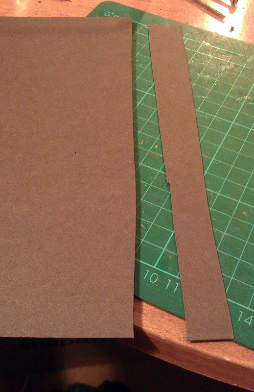
To give myself as much flexibility as possible with the design of the canyon only the ends and the small island supporting the junction turnout have been made from wood.  The fascia has been cut to follow the contours of the terrain.  The rest will be built up using my home-made rocks and plaster cloth.

Warsash Canyon Creation 0

The river bed was installed using a thick cardboard  The river drops ten scale feet from entrance to exit and the bed is propped with more cardboard and glued where possible to give a good solid base.  A basic white glue is good for this.

Warsash Canyon Creation 01

Next the basic structure of the landscape had to be built.  For this I used strips of cardboard from an old box.  I believe McCain oven fries were the flavor of the day!

Warsash Canyon Creation 2

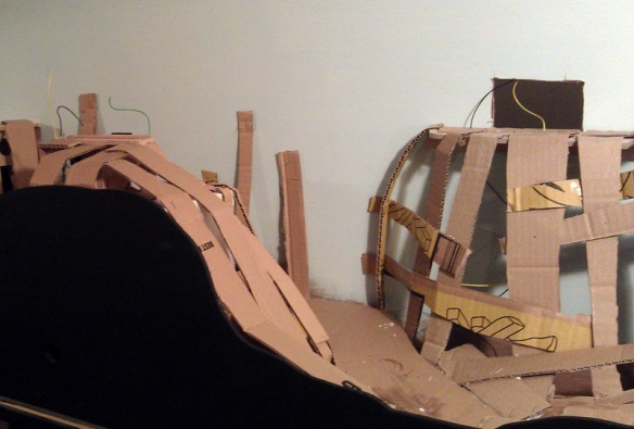
Even the back of the canyon had some card added up to the wall. The idea is to remove any large flat and square surfaces.  There is no particular science to this; it just needs to be a bit supportive and give the rough shape you want.

Warsash Canyon Creation 3

To give some stability to the structure another flat timber was added just under the hole in the back of the module where the branch line exits.  The timber was fixed securely to the back board and the cardboard strips could be fixed to it.  In the image below you can also see the timber island for the turnout. There is a Seep point motor under the timber.  The wires for track power were also installed at this point with lots of slack.  They could be added later but it’s easer to do this now.  The white you can see under the card strips on the left is a cube of polystyrene which had been glued to the inside of the fascia.

Warsash Canyon Creation 4

The strips of cardboard are glued together and I used a staple gun to hold it all together while the glue dried.  Where the strips meet the back board I used the staple gun for speed but still glued the ends to ensure strength.

Warsash Canyon Creation 5

Once all the card support was in place it was time to add the plaster cloth.  There are many manufacturers of this and I used a mixture of several I had to hand including Woodland Scenics and Mod Rock.  They are all basically the same although you may get a slight difference in color; this however is not a problem. The Mod Rock turned gray untill it had totally dried.

Although it’s lots of fun it can be a very messy activity so I didn’t take any photos of the work as it progressed.  I would also recommend putting some newspaper under the layout because you will get drips.

Warsash Canyon Creation 6

To apply the cloth you will need bowl of water, a good pair of scissors and be prepared to get your hands wet.

Warsash Canyon Creation 7

I cut the cloth into strips a little longer than the height of the canyon, then I dipped the strips into the water one at a time. Make sure you fully submerge the strips in the water. Then I draped them over the cardboard structure with each strip overlapping the last, helping to make the scene all one piece as well as strong.  The strips set fairly quickly and the shape of the canyon soon took form.

Warsash Canyon Creation 8

There is still some more to be added at the tunnel mouth but that will come later.  The deepest part of the canyon is where the river leaves the module and it is also quite narrow which made it a little tricky.  If you end up using lots of smaller sheets or simply adding several to ensure coverage that’s okay.

Warsash Canyon Creation 9

I put two layers of plaster cloth on some of the larger areas and staggered the joints, which adds to the strength and closes any holes which you can sometimes get when there is not much plaster on the cloth.  I then left the plaster to dry overnight, although it was probably dry within two hours.  At this stage I could simply paint the plaster rocky colors but I wanted to add the texture of a full rock face to the whole canyon.

This is where all the rocks I previously cast come in.

Lots of Cast Rocks

Taking some of the larger rocks I positioned them in ways that I felt looked natural.  This can take a bit of trial and error.  Once things started to fall into place I glued some of the larger ones down with white glue.  Then I was able to build up, adding more large rock castings and filling in around them with smaller ones.

Warsash Canyon Creation 10

By the time I had positioned rocks up to the level of the tunnel entrance I had also started to build up the cliff face to cover the tunnel.

I used some of the very large rock castings to form the steep canyon walls in the narrow section behind the turnout.

Warsash Canyon Creation 11

You will notice there are a lot of gaps between the rocks; this will be dealt with shortly but for now it is more important to make sure the rocks are firmly fixed in place.  Again I used white glue.  At this point I try not to get any of the glue on the face of the rocks as this will show when it comes to paint them.

Looking down the canyon the rocks looks rather out-of-place but this is how I intended them to look and once the next step is done they will look a lot better.

Warsash Canyon Creation 13

From a distance you can start to see how the rock face will look. I also glued in the outcroppings, for example the group to the bottom right of the photo below.  The rock glued to the back wall to the left of the unfinished area will form part of the tunnel opening.

Warsash Canyon Creation 14

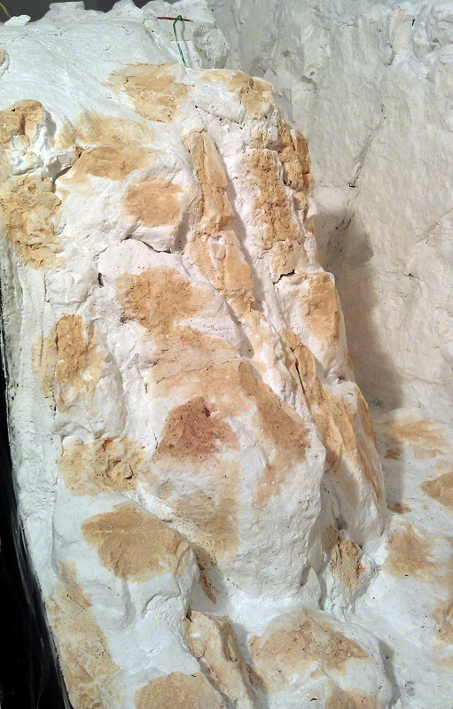
Once all of the rocks are in place, or at least most of them, and the glue has had a chance to dry, it’s time to seat the rocks and blend them all together.  I do this by using more plaster cloth.  I cut the cloth into strips roughly 25mm (1″) wide by 130mm (5″) long, then I dip each strip in the bowl of water and push the cloth into the gaps between the rocks.  Using my finger I smooth out the surface which brings the small plaster particles to the surface and hides most of the fabric.  I keep adding strips untill the rocks all start to blend together.  I try to encircle all the rocks making them look like they are all one big piece.

Warsash Canyon Creation 15

At this stage I had also finished the top section with the tunnel opening made from rock castings.  I wanted it to look like the railway engineers had cut the rock back to form the opening

Warsash Canyon Creation 16

Looking down the Canyon now the walls all seem to be part of the same rock formation.

Warsash Canyon Creation 17

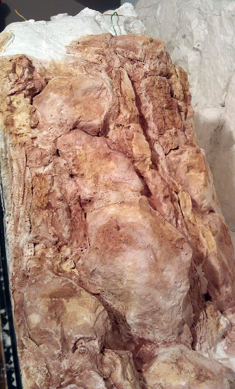
The rocks in the river bed also now seem to be a part of the landscape. And you can almost picture the river cascading down around them.

Warsash Canyon Creation 18

And again with the other end of the canyon I have placed rocks at the base of the walls and in the middle of the river bed.

Warsash Canyon Creation 19

There are still a few gaps but these will disappear once I start to color the rocks and add some greenery around the edges and in the cracks.

Warsash Canyon Creation 20

Overall I think the effect looks good. The next stage is to add some color but first the whole structure needs to dry.

Warsash Canyon Creation 21

In a later post I will share with you how to color the rocks to finally blend them all together as well as bringing out all the detail of the cracks and crags.

How to make your own NBWs for N Scale Trestles

Nuts Bolts & Washers (NBWs) can be an important detail on timber bridges or trestles and can make the difference in how good they look.  But in N Scale it can be a hard detail to achieve. There are commercially available products but if you need lots the price can start to climb.  In this post I will share with you how I make my NBW using a cheap and effective method.

Timber bridges and trestles are usually held together with long bolts which pass though the center of timbers at intersections.  The bolts are usually 3/4″ to 1″ in diameter and under the bolt head or nut is a 3″ or 4″ square cast iron washer.  The washer prevents the bolt head or nut from pulling into the timber.  Smaller joints are made with boat spikes which are similar large nails.

Below is a typical trestle bent I have scratch built for my new trestle module; the horizontal timbers will be fixed to the verticals using bolts.  The diagonals would have been fixed using boat spikes, however given the large number of bents I have to make I have decided to omit this detail.

NBW Blog Post 8

To make the washer plates I use black thick paper or card.  Using a sharp hobby knife I cut a strip off the side of the sheet the same width as one of the washer plates.  As this is for an N Scale trestle I have exaggerated the size of the washer plate to make them practical to work with;  mine are about 8″ to 9″ square.

NBW Blog Post 7

The strip is then cut into squares.  As my trestle project is fairly large I will be needing lots of these so to speed things up I cut several strips at the same time.  However when you cut a thin strip of paper like this it has a tendency to curl up so the trick to this is to leave the first and last part intact as in the image below.

NBW Blog Post 14

Then the paper can be rotated and all the strips can be cut through all together.  I hold the uncut strips down with my left hand as I cut with my right.

NBW Blog Post 15

To make the bolt and nut detail I use brown thick paper or card and a hole punch.

NBW Blog Post 1

The hole punch is a simple tool that came from a hobby cardmaking kit.  It is hollow so as the holes are cut the dots push up inside the tool.

NBW Blog Post 2

To add some thickness and variation to my bolt and nut detail I like to cut the paper into rough strips and place one behind the other before making the dots.  Sometimes I use two strips, sometimes three.

NBW Blog Post 3

When I use the punch I always use a separate cutting mat as it can be fairly destructive to them.  Below you can see where I have punched out a group of dots from two plies of paper.  The paper looks fairly disheveled, this is because as the punch cuts through the paper it spread it apart, keeping a perfect dot inside.

NBW Blog Post 4

The dots accumulate inside the tool.  Because of the asserted pressure to cut the dots the two sheets lightly fuse together making a nice thick dot.

NBW Blog Post 5

I keep my dots in a separate container from the washers; this makes it easer for me to quickly assemble my trestle parts.

NBW Blog Post 6

To fit the NBW detail I use Tacky Glue This is a white glue which is already fairly sticky and sets quickly.

NBW Blog Post 9

The particular brand of tacky glue has a nice dispenser on the bottle which allows me to put small dots where I want them.  Because it starts to set fairly quickly I only do about 10 at a time. Coincidently this trestle leg only has 10 bolts.

NBW Blog Post 10

Using tweezers I position 10 washers on the glue dots.

NBW Blog Post 11

Then I add another glue dot on top.

NBW Blog Post 12

Finally I add the brown paper dots on top of the washers.  A few of the dots will split apart giving a nice selection of thick and thin.  When the dots are positioned and pushed down some of the glue will rise up the side and glue the two parts together.

NBW Blog Post 13
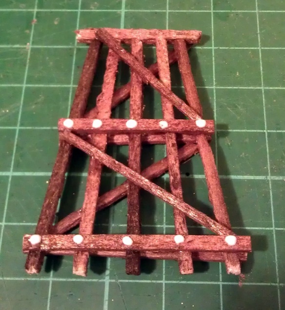
Once the glue has dried the NBW detail may look a little shiny; this is good because they would have been greased up to prevent them from rusting.

NBW Blog Post 16

If you also wanted to add the boat spike detail this can easily and cheaply be done by placing a small dot of black paint at the desired location with a tooth pick.  If the tooth pick is also pushed into the timber the indent will look like a spike head.

I have used this NBWs process with great effect for my whole N Scale trestle construction and I will share it with you once it is complete.

Drawing an Alco C-855 for N Scale Part 4

This week I’ve been working on the Alco C-855 project and I’ve assembled the chassis using the 3D printed metal chassis extenders.  In this post I will share with you how I did it.

You can read about the design for the metal and plastic parts for the extenders in my earlier post which you can find here.  The metal chassis extenders are required because the donor chassis, taken from a Con-Cor model of a GE U50, is not long enough for the huge Alco C-855.  The chassis extenders, pictured below, have been 3D printed in stainless steel.

C-855 Chassis Extenders 1

To start with the donor chassis is stripped down so only the two main metal parts are left.  It is best to remove any moving parts when cutting the chassis as metal filings can get into the gears and bearings causing damage at a later date.

C-855 Chassis Build 1

The two parts pictured above, along with the new sections, are ready to be marked for cutting.  I like to use a permanent marker to shade in the areas that need to be cut, as you can see below.

C-855 Chassis Build 2

Once I was happy with the marked areas I used a hack saw to cut the unwanted chassis sections out.  I will be providing instructions when these parts are released for sale with dimensions for where to cut.  Once removed the chassis sections looked like this.

C-855 Chassis Build 3

To fit the parts together I used a superglue but an epoxy will work just as well.  Because the parts are designed to fit together along a step it is fairly easy to get them in the right place. However it is still possible to fit them together at a slight angle so I recommend using straight edges as guides.  I used the back of a metal ruler for a base plate and my metal square as a side.

C-855 Chassis Build 9

I started with the top section and, as this is a test piece, I only glued one side first.  In the photo below you can clearly see the difference in size between the new section and the part that was cut out.

C-855 Chassis Build 7

Before I glued the other side of the top section together I wanted to check things were going right so I test fitted in the lower section of the chassis with the motor. As you can see from the photo below there was a slight problem.

C-855 Chassis Build 5

The motor appeared to be sitting too high in the lower part which looked to be preventing the top section from coming down squarely.  However after further inspection the motor was found to be in the correct place but the top section was a bit too thick.  This was caused partly by the rough surface on the unpolished stainless steel, and also because the superglue added a layer of thickness between the parts.  This was easily resolved by grinding down the underside of the chassis extender.  I used a sanding stone in a Dremel-style tool and removed some of the thickness as you can see below.  Interestingly the stainless steel is much harder than the metal used for the original chassis and it took a bit if working The metal got incredibly hot but the superglue joint held up with no problems.

C-855 Chassis Build 8

With the extension part modified the motor section now fitted properly, so I glued the other end on using the same metal square and ruler.

C-855 Chassis Build 10

The gap you can see in the picture below at the top of the right hand joint is because I slightly over-cut the chassis. However that is not problem as the step below is the part which correctly positions the extension.  I later filled this gap with more superglue.  I used the Gel Control Superglue made by Loctite which is perfect for jobs like this as you get a bit of working time before it dries and, being a gel, it will not run.

C-855 Chassis Build 11

Before moving on I also did some squareness checks as you can see below..

C-855 Chassis Build 12
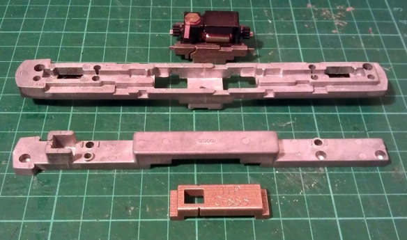
Now the top section was complete I could position and glue in the motor section.  You may have noticed I left the top and bottom sections of the chassis bolted together throughout most of this.  I did this to help ensure everything was in the correct place, particularly when it came to fitting the motor section.  As it happened I did cut the lower front chassis section a bit short and if I had glued the whole bottom section together tightly it would have been too short.  However as the chassis parts were bolted it all worked out well and below is the chassis glued together.

C-855 Chassis Build 13

Next I refitted the trucks and other internal parts ensuring there werre no metal fillings in any of the moving parts. I lubricated the motor, gears and drive shaft bearings and also put a strip of Kapton tape over the top motor brush connector.  It was ever-so-slightly touching the metal of the chassis extender and, as I proved in my prevision post, these stainless steel parts conduct electricity very well.  If this locomotive was going to be run as a DC locomotive this would be great but it will be DCC so I needed to isolate the motor.

Although the chassis extenders are great conductors the fact that I used superglue for the joints helped to form a perfect electrical barrier, so to ensure I get the benefit of all the power pickups, I bridged the chassis extenders using the original bolts, as you can see below.

C-855 Chassis Build 14

The two nearside bolts are in plastic sleeves so they don’t touch the top section of the chassis but conduct power from the bottom section.  The bottom section is connected to the right hand rail and the top is connected to the left.  To complete the test I also fitted a DCC decoder and the lighting and function wires are simply taped to the chassis for later use.

C-855 Chassis Build 15

The longer mechanism had no problem navigating some S bends and small radius turnouts on my switching layout.  I will also do a few tests on a bigger layout this week with a train in tow to see how it performs and I will share a video of that with you.

Below you can see some side by side comparisons between an original Con-Cor U50 chassis and my extended C-855 one.  The original chassis weighs 170g (5.99 ounces) and the extended one weighs 186g (6.56 ounces).  The C-855 did have 500 more horsepower than the U50 so this extra weight will help with traction.

C-855 Chassis Build 16 C-855 Chassis Build 17

I have now made some modifications to the chassis extension 3D model drawing to fix the issue I had with the first build. I will do one more test print before I make them available,, just to confirm that everything will fit together without modification.

The next step for the C-855 is to finish the 3D model for the shell and brass Additions.  Once I get them drawn up and ordered from the printer and etcher I will share them with you.