This weekend I was at the National Model Railroad Association’s (British Region) annual convention. And over the next few weeks I will be sharing with you some of the fantastic layouts that were on display. However this first post will be short as I only arrived home late last night and need a bit of time to work through all the images and videos.
This year’s event was hosted by the Black Diamonds model railway group and they did a fantastic job of organizing this great convention.
What I can share with you this week is a little bit of history about the venue. The convention was held at the Derby Convention Centre which used to be the London Midland & Scottish Railway (LMS) training school. Built in 1938 and designed by the LMS’s principal architect, William H. Hamlyn, it was the first of its kind in the UK. The facility could house 50 trainees plus staff who taught the complicated practice of railway signalling. The building has now been converted into a conference center but the layout and general feel of the building has not changed.
As well as all the classrooms and facilities around the building there is a large hall at the center with a sunken floor as pictured below.
This room had a very special function in that it housed a large model railway which was used by the LMS to teach the complicated process of signalling. Below is an image of the layout running along the sides of the sunken lounge.
The layout was removed in the 1960s and is now part of the national railway collection housed at York. This room was used as the central point for the convention and as you can see below the sunken lounge was again full of railways, or in this case, railroads. And the big layout in the middle is my group’s layout, ‘Solent Summit’.
One other thing I want to share with you this week is a small purchase I made at the show.
It’s an Alco C-628 in HO made by Bowser. No this doesn’t mean I am switching from N Scale to HO, but a few of you may be interested to know that this will be the new chassis for my HO Scale Baldwin DT6-6-2000 and RT-624 locomotives!
In next week’s post I will be sharing with you some of the layouts from the show.
With the NMRA (BR) Convention coming up this weekend I decided that some of my running stock needed some attention before the show. A lot of my older rolling stock still has the Rapido style couplers and some of the newer stuff has Atlas’ Accumate couplers. My preference for couplers has always been to use Micro-Trains as I have found them to be the most reliable. In this post I will share with you how I convert older rolling stock to MT couplers in a fairly cheap way.
The box car below is a typical 40 foot car with Rapido couplers fixed to the trucks. By far the simplest way to convert this car would be to buy a set of MT trucks, which come with couplers pre-mounted, to replace the originals. However this can become very expensive if you have lots of cars to convert.
Another slightly cheaper alternative is to buy an MT conversion kit that will replace the coupler in the truck. These can be a bit tricky to fit but work very well and you get to keep the original wheels. The car I’m converting has metal wheels which are clean and in good order, making it a good runner.
For me the cheapest option is to use body mounted couplers. Again this means you get to keep the existing wheels and trucks but the existing couplers are removed totally. The new couplings are fixed to the underside of the car chassis. This is actually more prototypical and transfers the weight of the train through the chassis, bypassing the trucks and bolster pins.
The MT body mount couplers are available in pairs or in bulk packs as shown below which is certainly the cheapest way to buy them.
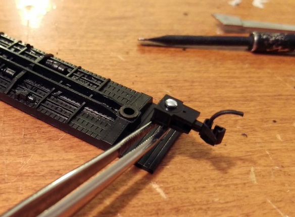
To make the change you will need a few basic modeling tools as shown below. I use a small watchmaker’s screwdriver, flat file, craft knife, needle nose tweezers, flat end tweezers, MT gauge, pin vice with a drill (from the MT Tap & Drill Set – 00-90), side cutters & pliers.
To start you should check that the car is in good running order. You can see I have already changed the left hand coupler.
The body should simply pull off the chassis and can be put to one side.
While the body is off it’s a good chance to check that the weight inside the car is properly secured; it’s normal for this to be rusty as it’s simply a strip of unprotected steel. If the weight is loose simply glue it back into place before continuing.
Next remove the truck by pulling out the bolster pin. You can do this either with the pliers or by simply pulling on the truck. Make sure the bolster pin does not fly off.
With the truck removed the front wheel set can be taken out by gently pulling the truck side frames apart.
Then using the side cutters snip off the coupler leaving enough material surrounding the bolster pin hole. You won’t be able to do this in one snip as the truck side frames will be in the way. I find five snips normally does the trick. Once finished the top of the truck needs to be flush otherwise it may hit the new coupler. If the area where you sniped is a bit rough you can use the file to smooth it out.
The truck can then be loosely re-fitted, there is no need to push the bolster pin in hard as it will be removed again shortly.
The bulk pack of couplers contains lots of parts but to assemble one coupler you need the five laid out below. They are the coupler hook and catch plate, coupler box and top plus a spacer, screw, spring and drop pin.
Using the craft knife remove the coupler hook and catch plate as well as the coupler box and top from the sprues. The spacer is the flat part on the right and may be required later so put it to one side.
With the parts removed there’s one small thing I like to do before assembling the coupler and that’s to use the file to deburr the top of the drop pin. This simply makes it fit easily without too much force which can break the coupling hook. The end that fits into the coupler hook is the longer leg.
I tend to hold the pin in the tweezers or pliers and run the file on four sides of the pin at 45°.
With the pin still in the tweezers or pliers push the filed end into the small hole in the coupling hook. The pin should be at an angle which is parallel to the side of the hook. The pin only needs to go through the hook so the end is just poking out of the top.
With the pin fitted slide the coupler catch plate over the pin.
With the coupler box on its back place the assembled parts over the tube in the box.
The next part is the most tricky. There are several ways of doing this but for me I like to use a pair of needle nose tweezers and a watchmaker’s screwdriver. The risk is that the spring will ping off and, given how small these are, you usually can never find it. Luckily MT provide several spares in the kit. I find it’s best to get the spring close to the coupler and almost in the same orientation. Then carefully compress the spring with the tweezers and place it over the slot between the coupler box tube and parts. Using the screwdriver push the spring down into place and release the tweezers.
Once in, the spring will stay there, but the assembly is very delicate so don’t knock it or the spring may ping out.
Using the tweezers place the box lid on to the box and press down with your finger. It should clip into place. The lid only fits on one way round and the underside has groves to fit onto the box.
Once the lid is clipped on the coupling is fairly robust and can be moved about. Check that the coupling moves in the box and bounces back to the same central position.
Now it is time to fit it to the car chassis. The particular set I am using are medium length, for a 40 foot box car. A short length might have been better but they will work just as well.
Place the coupling on the underside of the chassis and pass the drill through the box tube. Once the coupling is as far back as you want it, ensure the truck can rotate and the coupling is centered, and use the drill to mark the chassis.
Then remove the coupling and truck so you can easily drill through the chassis. Depending on the make of the car the distance from the edge will vary, but I tend to find the hole needs to be halfway between the third and forth plank counting from the edge. As this car has a plastic chassis the metal screw will cut its own thread. However if the chassis is metal you may want to use the tap that came with the MT tap and drill set to cut a thread in the chassis.
Next push the screw into the coupler box hole from the underside.
I find pushing the screw all the way though and holding it with the needle nose tweezers helps keep the screw straight when you start to tighten it up.
Once the screw is started you can let go with the tweezers and tighten it up. Make sure the coupler is square before you fully tighten it. You will notice that the screw is now sticking through the floor of the chassis. This is not a problem as it will be inside the box car but if your car has a veranda, such as you get on a caboose, or is simply a flat car, you will want to shorten the screw with the side cutters first. Note: you will also need to use a big set of side cutters for this as you may break a modeling pair.
The truck can now be installed. If the truck can rotate freely push the bolster pin in all the way and refit the wheel set.
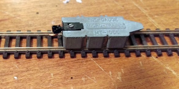
The last thing to do is check the height of the coupler. Using an MT gauge as shown below this is very easy to do.
Simply clip the gauge to the track, shutting off the power first, and test the new coupling with it. Should the coupling be too high simply unscrew the coupling and add the spacer that we put to one side earlier. This will lower the coupling. In the unlikely event that the coupling is too low then remove the trucks and add a washer to each; this will raise the whole box car correcting the coupling height.
The box car is now ready for service.
As I said at the beginning the NMRA (BR) Convention is this weekend at Derby, England and I will be there along with my fellow modelers running the N Scale modular layout ‘Solent Summit’, and my new modules will be there. The convention is open to the public on Sunday and it would be great to meet anyone who is coming along. If you can’t make it I will be giving a full report here in the coming weeks. This week I will leave you with a taster from my new modules, below is a video of a ‘short’ train crossing the Warsash River on the Warsash Wye trestle.
One of challenging things about soldering wires onto switches and components is not having enough hands. Trying to hold the soldering iron, wire, switch and solder can be a bit tricky at times so in this post I will share with you a simple tool I have found to help.
I have used this tool for all sorts of things from Seep point motors to Din plugs. The advantage the tool gives you is it has a firm shell and a soft inner similar to a pin cushion. This allows you to stick or plug the item you need to solder wires to into the tool leaving your hands free to solder on the wires. With items like Din plugs that are small and have lots of wires this is particularly usefully as without the tool the wires you’ve already soldered on will tend to pull the Din plug away from where you need it. The tool will keep the plug in the same place.
This tool is available at just about all local shops, is very inexpensive and comes in a variety of sizes. Although you will have to get a new one on a regular basis I recommend getting a bigger one as the smaller ones tend to roll around too much.
So what is this amazing tool? Well, it’s a potato!
As you can see in the photo below the long bar that is used to throw the points on this Seep point motor has simply been stuck into the potato making it very easy to solder on all the wires. The circular hole patterns are from the Din plugs that were made up earlier. A smiley faced potato is not a necessity but it can brighten your day!
As I said before it is a good idea to regularly change your potato tool, particularly if it turns green!
We are now only two weeks away from the this years NMRA (BR) convention so it’s back to the modelling for me to get my modules finished in time but after the show I will be back to 3D printing and progressing some of the projects.
As I am now nearing the end of my module build I am concentrating on some of the details that make my modules realistic. I have already shared with you how I ballast my track and you can read about it here. In this post I will share with you how I ballast my track up to trestle ends where the ground suddenly drops away.
In the model world the ballast is glued down so there is no problem placing ballast right on the edge of a drop as the glue will hold it in place but in the real world wind, rain run off, train vibration and general movement will cause the ballast to fall of the edge creating a weak spot in the trackage. Where the ground gently slopes away, as in the image below, this is less of an issue as the ballast will simply form a shoulder; as it does on the sides of the track.
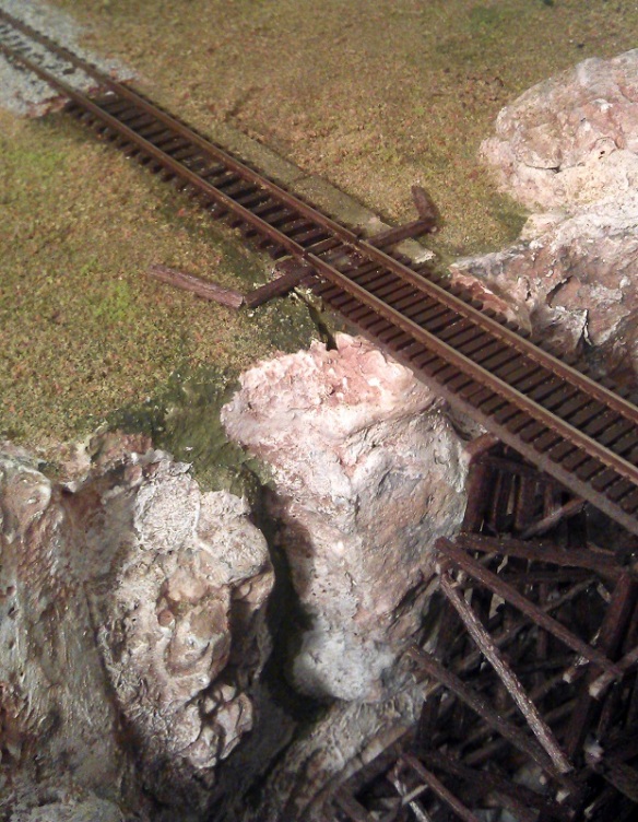
However areas where land drops of steeply or as in my case vertically the ballast needs to be contained. There are all sorts of ways to do this from using concrete to earth banks but as my trestle is made from timber it would make sense that the containing barrier would be made from timber as well. As you can see in the picture below I have created a C shape where the trestle starts.
There would be no timber between the rails because the bridge ties will provide the required barrier. I have repeated this at all the trestle ends where the land drops away as you can see in the images below.
The timber has simply been glued to the scenery using white glue. Once the glue had dried it was time to add the ballast and using the same techniques as before I ballasted up to all the barriers.
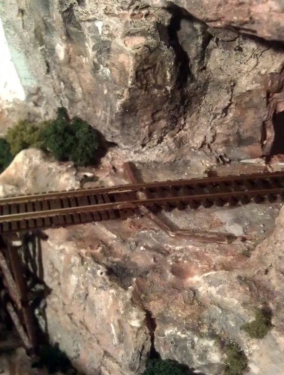
With the trestle end meeting the land on a gradual slope the ballast simply runs into a shoulder as you can see below. The end of the trestle is founded on a timber frame full of rock and ballast that has been cut into the bank.
The overall effect is a well ballasted track section with clean bridge track.
The final stage to complete the trestles will be to add the check rails and safe refuges which I will cover in a later post.

 As well as all the classrooms and facilities around the building there is a large hall at the center with a sunken floor as pictured below.


You must be logged in to post a comment.