This week’s post will be brief as I’m in the middle of preparing for my club’s upcoming exhibition on the 20th of October. I’ve been the exhibition manager for the show the last three years and the preparation almost consumes the weeks running up to the show, but the hard work is most definitely worth it as we’ve been able to provide consistently good quality model railway shows as a club. We have 18 exhibition layouts coming this year including:
Any City – OO
Atherfield – OO
Brixham Bay – N
Cringle Street – O
Denver, Gosport Gulch & Pacific Railroad – ON30
Flintcombe – P4
Freshwater – N Scale
Garreg Wen – OO9
Great Swilling – EM
Kamiak Falls – HO
Milford on Sea – OO
Millway Dock – OO
Newquey East – OO
Parkstone Goods – OO
Rookery Lane – OO
Santa Agueda – HO
Springfield – O
Svanda – HO
We will also have good trade support and several demo layouts and displays, and once again our main sponsor is Model Railway Solutions, a fantastic modeler’s shop and source of info in our area!
If you’re in the area that weekend, come along, it promises to be another great show and we’d love to see you.
As well as producing 3D printed parts I also help solve problems on layouts, and one problem which arises is locomotives and rollings stock not running smoothly through turnouts and crossings. This is often due to the distance between the wheels, or back to back, not being correct. In this post, I’ll show you how I check and adjust this.
Railway wheels, irrelevant of size and design, all have the same basic parts. An axel, tire, rim, and flange. The tire rides on the rails, and is held in place by the rim. The flange sits inside the tire and the axel holds both wheels together, forming a wheelset.
The tire is actually tapered which causes the wheelset to sit centrally between the rails. As the wheelset rolls along it will naturally center itself due to gravity.
But as wheelsets round a curve a centrifugal force will try to push the wheelset off the rails towards the outside of the curve. As the wheels go faster the centrifugal force gets larger and will eventually overcome gravity, but the flange prevents the wheel from going past the rail.
The distance between the rails is fixed, as is the distance between the flanges. This distance is called the back to back. Wheelsets will run if this distance is wrong, providing the flanges fit between the rails, but the problem comes when the wheelsets need to pass through a turnout or crossing. The distance between the parts of the turnout is specifically set, and if the back to back is not right the one wheel will run in the correct place and the other will bind, jam or ride up over the rails causing a derailment.
With model trains, unlike the real thing, wheelsets are either made entirely from plastic or metal where the wheels have to be electrically isolated from each other so as not to short. The real railways like electricity to pass through the wheelsets as they use that for train detection. The plastic wheelsets, as shown below, are usually injection molded in one piece and very accurately. So unless they’re damaged the back to back dimension should be correct.
Metal wheelsets, as shown below, either have one or both wheels isolated from the axel. This wheelset has a plastic isolator between the far wheel and the axel.
The problem here is the wheel on the far side can sometimes move on the axel as the plastic isolator is only held in place by friction. This changes the back to back dimension. Also some manufacturers have better quality control than others and it’s not unheard of for a brand new item of rolling stock to be incorrect right out of the box.
So how can this be fixed? As always in model railways, there are several ways of doing the same thing, but for me, I like to use a gauge. The NMRA (National Model Railroad Association) supply gauges for all the major scale and these include back to back checks as well as many other things for checking turnouts etc. The gauges are also the same size as the loading gauge for that particular scale so you can check tunnel heights and platform clearances etc.
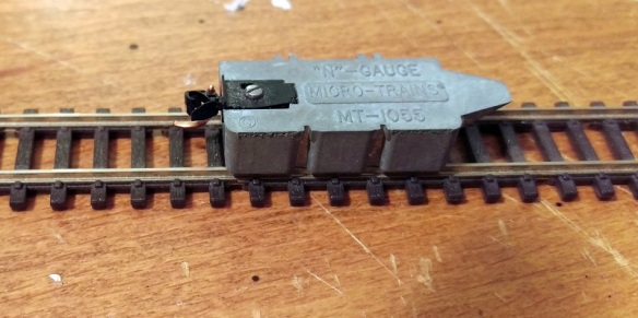
Another tool I tend to use for N scale is the Micro-Trains coupler height gauge. I’ve written about this before in my post about fitting Micro-Trains body mount couplers to older N Scale freight cars, which you can find here.
As well as being a coupler height gauge, it also has a wheel back to back check and a rail spacing check. In the image above the wheel back to back check is on the near side and the rail spacing check is on the far side.
To use the gauge, simply put the wheelset into the slots; if they fit they are correct. The set below is clearly out of tolerance.
As the wheel at the bottom of the image is fixed to the axel it’s the one at the top with a plastic isolator which will slide, and using a pair small pliers I can easily slide the wheel up until it’s in the right place.
You don’t have to take the wheelset out of the truck to check it when using either the NMRA or Micro-Trains gauge, but if you need to adjust the wheel back to back I would recommend taking it out as the pressure could easily damage the plastic truck.
With all your wheelsets back to back correctly adjusted you should find your trains run nice and smoothly through your track work.
Back in July, I shared with the second part in my design of a dummy knuckle coupler for OO gauge rolling stock. You can find the post here. Since then the first prints have been through several tests and they performed very well. In this post I’ll show you the small changes I made to the design and share with you how to get some.
The original design, as shown below, was printed in both Shapeways clear Fine Detail Plastic and the Black Versatile Plastic. The Black Versatile Plastic turned out to be so good I’ve carried on with only this material. Not only is it strong, but as it’s already the right color, they’re ready to use.
The original design was for a dummy knuckle coupling which would work with Kadee couplings as well as each other.
The first issue I had with them, albeit a small one, was with the knuckle section. As the actual knuckle, unlike the Kadee, doesn’t swing, and it tended to grip on tight curves. I opened the jaws slightly to allow a bit more movement. This solved the issue.
The second issue was due to height. As I’ve said in other posts about couplings, despite there being the NEM standard regarding couplings and height, different manufacturers have positioned their coupling pockets at different heights. Some seem to be high and some low, which leads to the situation of an uncoupling, especially on gradients as the rolling stock crosses the transition from flat to inclined. My first answer was to offer three different types, as shown below; high, standard and low.
However given there may be a few different lengths, this makes for a large number of different couplings to manage.
A much simpler idea was to make the knuckle 2mm bigger. By moving the top up by 1mm and the bottom down by 1mm all versions are covered. The wings either side of the knuckle were also removed as they performed no real purpose.
This new design was 3D printed on sprew in the Black Versatile Plastic. The sprew helps reduce the cost of the parts.
The Bachmann OO Class 66 has, what I consider, to be a correctly positioned NEM socket, that is, it’s in the middle of all the rolling stock I’ve tested. The new coupling fits perfectly and doesn’t look too out of place.
Compared to a standard Kadee in another Class 66, the new coupling looks okay, even if it’s a bit deeper.
The two coupled perfectly and as you can see the new coupling sticks up and down by 1mm, ideal if the coupled item of rolling stock has its NEM socket out of place.
This coupling length is based on a Kadee No. 19. which works well for most items, although I found Hornby coaches ended up with a larger gap between them than I liked, so a shorter version will be designed soon.
For now, these are available in packs of 10, 25, 50, and 150 and you can find them using the links below.
Once the length of a shorter coupling has been finalized, to reduce the gap between Hornby coaches etc, I will share this with you too. But now it’s back to the drawing board as I have several projects to wrap up which I’ll also share with you in due course.
Several weeks ago in July I shared with you my install of ESU Loksound sound decoders into a set of my Alco C-855 locomotives, you can find the post here. Then in August, I showed you how I improved the running of the locomotives by adding some stay alive capacitors, you can find that post here. In this week’s post, I’m going to share with you the final step which is setting up the sounds for multiple engines.
Most suppliers of ESU sound decoders give you a choice of sounds when you purchase the chip and they will load the sounds on for you. But to add your own sounds or load on a downloaded sound scheme you need an ESU Lokprogramer and the accompanying software. These, along with a computer, will allow you to change all of the settings of the decoder.
However, they can be fairly expensive so if you have your decoders with pre-loaded sound schemes you can use other devices to adjust the settings. For example, although I use a LokProgrammer I also use a Sprog II from sprog-dcc and the DecoderPro software from JMRI. The Sprog II is relatively cheap and the DecoderPro software is free to download. Together they will allow you to edit the setting of just about any DCC decoder but please note it will not allow the upload of sound files.
The sound file for the C-855 was downloaded from the ESU website and comes with all the normal functions such as horn, bell, coupling, etc. The new versions also come with ESU’s Full Throttle settings. These include features such as Drive Hold, Independent Brake, Run 8 and Coast.
These functions can be fairly complex but in short, they work like this:
Drive Hold when pressed keep the model motor running at the same speed and as the throttle is increased or decreased the revs of the engine changes. Ideal if you are pulling a slow heavy train uphill and you want it to sound like it’s working hard.
Independent Brake when activated slows the train to a stop without adjusting the setting on the throttle, when released it speeds up again to the throttle setting.
Run 8 when activated increases the sounds of the engines to maximum revs irrelevant to the speed of the train. This is great when simulating a heavy train about to start moving and is my favorite Full Throttle function.
Coast reduces the revs of the engines to tick over irrelevant to the speed of the train. This is great when running downhill or for light loco movements.
Out of the box, only the Drive Hold & Independent Brake are set up as you can see from the function list below:
F0 Directional Headlights
F1 Bell
F2 Playable Airhorn
F3 Coupler
F4 Dynamic Brake
F5 AUX3 (Rotary Beacon)
F6 AUX1 + AUX2 (Front Ditchlights)
F7 Switching Mode
F8 Sound (On/Off)
F9 Drive Hold
F10 Independent Brake
F11 Radiator (Fan) Sound
F12 Dimmer (Headlights)
F13 AUX4 (Rear Ditchlights)
F14 N/A
F15 Fast Spitter Valve
F16 Spitters on Shutdown
F17 Brake Set / Brake Release
F18 Sanding Valve
F19 Short Air Let-Off
F20 Compressor
F21 Slow Spitter Valve
As standard one of the first things I like to do for my trains is set the Run 8 function to the F5 key, as I don’t put rotary beacons on my models this key is free. I will show how to do this first using the LokProgrammer and then with JMRI through the Sprog II. One thing to note, it’s a good idea to save the setup before you alter it, that way if everything goes wrong you have a backup of the original settings.
In the LokProgrammer software, you can see what each function is assigned to in the function mapping tab. As standard F5 is set to AUX3.
I change this as shown below. I have also set F6 up as the coast function.
Sometimes, if you’re reading the settings form the locomotive rather than a downloaded file, the name of the sound does not appear, just the slot number. By default Run 8 is normally sound slot 20 and Coast is sound slot 21. The changes can then be written to the decoder.
With DecoderPro the process is similar but it takes a little longer as you need to read all the settings from the decoder before you adjust any, otherwise you could overwrite something you didn’t want to. (Please note the Decoder Pro Screenshots are from a different loco).
With the F5 & F6 corrections made the screen looks like this.
Normally that is enough setting up and here is a short video of a single C-855 staring up, then having the engines run with Drive Hold on and lastly the Run 8 function. Because the C-855 had two diesel engines you here the first fire up then the second. Also both engines run at slightly different speeds so they are not simply copies of each other, I will explain more about that later.
As the same sound file has been installed in all three locomotives, the two C-855s and the C-855B, all three locomotives are running on the same DCC address so they all respond at the same time, as you can hear below.
The volume is much louder as we now have three speakers pumping out the sound but the problem is although the two engines in each locomotive are running a different speeds, each locomotive sounds exactly the same. And I don’t think Alco managed to achieve that! So in order to improve the realism, I will set each of the six engine sounds so they all run at there own speeds. The change doesn’t want to be much, but a little adjustment can make all the difference. The great thing about the ESU decoders is you can make adjustments to individual sound files without affecting the overall sound. After all, we want the bells and horns to be the same across all three locos.
With the LokProgrammer on the function mapping page F8, which turns the sound on and off, controls two sound slots called ‘Dual-ALCO-16cyl-251C-FT-PM#1’ and ‘Dual-ALCO-16cyl-251C-FT-PM#2’.
Clicking on the drop-down menu these are sound slot 1 and sound slot 23.
Switching to the ‘Sound Slot Settings’ tab the setting for all the sound slots can be adjusted.
As you can see below sound slot 1 has a maximum and minimum value of 126, which is 98.44% of the original speed.
But sound slot 23 is set to 130 which is 101.56% of the original speed. And that’s how the two engines run at slightly different speeds.
So for the three locomotives, I will set the sound slots up as follows.
Of course, the difference between the locomotives could be increased to give an even more noticeable difference, the difference is a personal preference.
With Decoder Pro these settings are in the ‘Sound Levels’ tab. Again you will need to read all the settings from the decoder first but you can save them so you don’t have to read all three locomotives. As with the LokPrograammer software the ‘Function Map’ tab will tell you which sound slots are operated by function F8.
Sound files for the Mallet and articulated steam locomotives, such as the Big Boy, use the same system to archive slightly different chuff sounds for each set of cylinders.
There are lots of settings available with these decoders which allows you to customize your locomotive, or as in this case a set of three.
These C-855s are now finished and ready to rumble their way up the track.
Next week I’ll be looking at the next step in my OO NEM dummy knuckle couplers.
It’s been a few weeks since I last posted, but don’t panic I’m still here! It’s been a busy summer, and as we neared the end of it I expected things to be a little quieter but I’ve been working at show and exhibitions supporting my wife’s business, which I hope will enable me to increase my purchase of trains and train-related travel!
Next week I’ll be back to my normal posts but for this week I just wanted to check in and let you know about a couple of shows which I’ll be at.
On October 20th the Poole Model Railway exhibition will be at the Poole Grammar School in Dorset. You can find more about that here.
Along with my fellow modellers from the Gosport American Model Railway Group we’ll be taking all of our modular N Scale layout ‘Solent Summit, to the ‘WARLEY NATIONAL 2019′ show on the 23rd-24th November at the NEC in Birmingham. You can read more about the show here. The ‘WARLEY NATIONAL 2019′ is one of the largest shows in the country which is why we can take such a big layout. With five scale miles of scenery, Solent Summit will be 65′ by 30’.
So if you’re coming to either of the shows I’ll see you there.
And as promised next week I’ll be back to my regular posts.


You must be logged in to post a comment.